Edwards FX-PDD Addressable Duct Smoke Detector Installation Sheet
File Preview
Click below to download for free
Click below to download for free
File Data
| Name | edwards-fx-pdd-addressable-duct-smoke-detector-installation-sheet-2087561934.pdf |
|---|---|
| Type | |
| Size | 1.49 MB |
| Downloads |
Text Preview
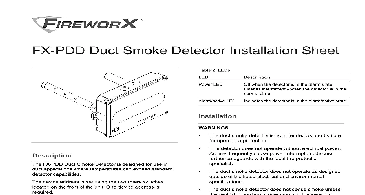
Duct Smoke Detector Installation Sheet when the detector is in the alarm state intermittently when the detector is in the state the detector is in the alarm active state 2 LEDs LED LED duct smoke detector is not intended as a substitute open area protection detector does not operate without electrical power fires frequently cause power interruption discuss safeguards with the local fire protection duct smoke detector does not operate as designed of the listed electrical and environmental duct smoke detector does not sense smoke unless ventilation system is operating and the sensor is properly installed duct smoke detector may not operate as designed installed in accordance with these instructions all applicable national and local codes as by the local authority having jurisdiction Read these instructions thoroughly before installing to Technical Bulletin P N 3101107 for additional regarding installation instructions guidelines ensure correct operation install the duct detector using following guidelines the duct smoke detector on a flat section of duct between six and ten duct widths from any or obstructions supply side detectors at a point downstream from supply fan and after the air filter return side detectors at a point before the return stream is diluted by outside air the duct air velocity order to verify the airflow direction and velocity air must moving through the HVAC system FX PDD Duct Smoke Detector is designed for use in applications where temperatures can exceed standard capabilities device address is set using the two rotary switches on the front of the unit One device address is installations where the controls and indicators are hidden view a remote test station or an LED indicator can be to the detector to provide these functions settings following jumper settings determine the operation of the See Figure 6 for proper jumper location 1 JP3 jumper settings the detector for alarm latching the detector for supervisory is the factory default setting operation LEDs visible from the front of the detector show its 2013 UTC Fire Security All rights reserved 6 3101069 REV 03 REB 23JAN13 verify the duct air velocity Drill a small hole at the point where the duct smoke is being installed Using the SD VTK Air Velocity Test Kit and a suitable velocity meter verify that the air velocity in the HVAC falls within the specified operating range of the and note which direction the air flows the air velocity does not fall within the specified range the detector and seal the hole in the HVAC Refer to Technical Bulletin P N 3101107 for information pertaining to installation locations an appropriate sampling tube a sampling tube that extends at least two thirds the width of the duct Refer to Table 3 below duct widths greater than 36 inches use a sampling that is longer than the width of the duct tubes are available in the following lengths 3 Sampling tubes in in assemble the detector Assemble the duct smoke detector as shown Figure 1 Rotate the air sampling tube so the inlet holes face the of airflow The sampling tube is normally installed from the rear it can also be installed from the front of the detector shown in Figure 2 This method requires that you the detector cover 1 Duct detector assembly Plug Thick gasket Thin gasket Exhaust tube Exhaust tube socket Sampling tube socket Detector Coupling Sampling tube 2 Sampling tube installation Sampling tube socket Detector Sampling tube fully assembled install the detector Attach the drill template to the HVAC duct at the desired location Drill or punch the mounting holes where indicated Remove any rough edges from the holes 6 3101069 REV 03 ISS 23JAN13 When using an air sampling tube that is longer than the of the duct Drill a 3 4 in hole on the opposite side of the duct the tube to pass through Cut the tube so that approximately one inch of the extends through the duct Seal the opening the tube with an approved duct sealant as in Figure 3 Support sampling tubes longer than 36 inches at ends of the duct See Figure 3 Mount the duct smoke detector on the HVAC duct and it using the two sheet metal screws provided Figure 4 Verify that all field wiring is free of opens shorts and faults Make all wiring connections as shown in Figure 6 Set the module address as follows Use a screwdriver to adjust the two rotary switches the front of the module See Figure 5 the TENS rotary switch 0 through 12 for the and 100s digit the ONES rotary switch for the 0 through 9 example for device address 21 set the TENS switch to 2 and then set the ONES rotary switch 1 a list of detector addresses see Table 4 below Verify that the air pressure differential value falls within specified operating range of the detector in with procedures specified in the pressure differential on page 5 After completing the installation of the duct smoke test the detector in accordance with specified in the duct smoke on page 5 to ensure it is operating correctly 4 Detector address to 64 to 127 point control panel point control panel Set jumper JP3 to the appropriate position See Table 1 Figure 6 3 Sampling tube support 36 in 0.92 m HVAC duct Exhaust tube Detector Sampling tube Airflow Plug Sealant 4 Duct detector installation 10 sheet metal screws 2X Sampling tube Airflow HVAC duct Detector 5 Address switches 6 5 9 screwdriver here 3101069 REV 03 ISS 23JAN13 6 in accordance with NFPA 72 and CAN ULC S524 Be to observe the polarity of the terminals on the terminal as shown in Figure 6 6 Duct detector wiring 3 4 Auxiliary equipment Power limited unless connected to a Remote alarm active indicator See on page 6 for source If the source is nonpower limited the power limited mark and maintain a minimum of in 6.4 mm space from power limited wiring For other methods see enclosure and bracket installation sheets maintain separation of power limited and nonpower limited The wire size must be capable of handling fault current the nonpower limited source type FPL FPLR FPLP or permitted substitute cables that the power limited cable conductors extending the jacket are separated by a minimum of 0.25 in mm space or by a nonconductive sleeve or nonconductive from all other conductors The wire size must be capable handling fault current from the nonpower limited source Refer NFPA 70 for more details or list of available model numbers Connect only one remote test station or LED indicator to the Wiring is unsupervised Maximum wire resistance is per wire Remote test station See on page 6 for a list of model numbers Power indicator Alarm Indicator JP3 shown in the factory default position for supervisory mode Alarm position Supervisory position 6 3101069 REV 03 ISS 23JAN13