Edwards GCI Graphic Annunciator Interface Card Installation Sheet

File Preview
Click below to download for free
Click below to download for free
File Data
| Name | edwards-gci-graphic-annunciator-interface-card-installation-sheet-4869352701.pdf |
|---|---|
| Type | |
| Size | 1.08 MB |
| Downloads |
Text Preview
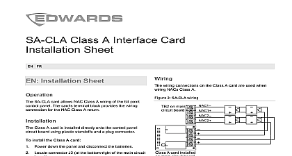
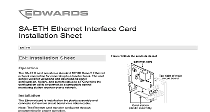
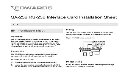
Graphic Annunciator Interface Card Sheet ES FR PT Attach the GCI card by screwing the mounting track to the It is not necessary to remove the GCI card Set DIP switch S1 as required See switch settings details Connect the field wires switches and LEDs as required on page 2 for details you are connecting a remote key switch remove the from the EXT SW pins and attach the remote key connector to the pins switch settings GCI card provides an 8 segment DIP switch for setting the address the baud rate and the type of annunciator circuit which it is connected Switch segment 8 is not used address switch segments 1 to 5 to set the GCI card card address binary as shown in Table 1 below Possible vlaues 1 to 31 For address 3 set S1 1 and S1 2 to the ON position set S1 3 S1 4 and S1 5 to the OFF position 1 Card address settings S1 3 S1 4 S1 5 Description 1 2 4 8 16 ON O OFF rate switch segment 6 to set the GCI card baud rate as in Table 2 on page 2 This setting must match the baud setting on the control panel Installation Sheet GCI Graphic Annunciator Interface Card connects a UL ULC Listed fire alarm control panel FACP to LED based graphic annunciator GCI card provides dedicated switch inputs for common controls programmable switch inputs dedicated LED outputs for power common system status and enable controls indicators programmable LED outputs for zone or device indicators buzzer that sounds when the control panel activates an GCI card does not provide ground fault isolation GCI card ships with a mounting track and connector GCI card can support up to eight GCIX graphic expanders however this number is determined by control panel 2011 UTC Fire Security All rights reserved 14 3100973 ML REV 2.0 ISS 16MAR11 2 Baud rate settings Description other baud rates baud default ON O OFF 1 Terminals and connectors circuit switch segment 7 to select the annunciator circuit type as in Table 3 3 Annunciator bus settings Description supports Class B and Class A wiring supports Class B and Redundant Class B wiring ON O OFF 2 Annunciator circuit wiring 3 AUX power riser wiring IN OUT IN OUT IN OUT CH1 IN from the control panel or previous annunciator to the next annunciator or to the control panel if the annunciator on a Class A circuit CH2 IN from the control panel or previous annunciator to the next annunciator Used only on redundant B circuits Use the control panel power supply or a 24 VDC continuous power supply that is UL ULC Listed for fire protective systems 14 3100973 ML REV 2.0 ISS 16MAR11 4 Remote key switch wiring Remove the jumper installed on EXTSW only if you are a remote key switch 5 Switch and LED wiring and LED terminals are listed in Table 4 and Table 5 4 Switch terminal definitions to J7 8 SW SW Silence SW SW Test SW used to J7 12 to J8 12 1 to SW 4 5 to SW 16 5 LED terminal definitions LED Silence LED LED Fault LED LED Enable LED LED Test LED LED Alarm LED LED to J2 8 used 1 to LED 8 to J3 8 9 to LED 16 to J4 8 to J5 8 17 to LED 24 25 to LED 32 to J6 8 factor inputs collector outputs current wiring circuit key switch fault environment size rate humidity VDC mA at 24 VDC mA at 24 VDC dedicated 21 total contact LED driver use only mA at 5.7 V input max 1.0 resistive 11 zone or programmable 32 mA at 5.7 VDC per LED typical to 18 AWG 1.0 to 2.5 mm B Redundant Class B or Class A to 14 AWG 1.0 to 2.5 mm pair 6 twists per ft min ft 1,219 m max to 115200 baud VDC at 1 mA power limited unsupervised 10.25 1.50in 8.3 2.6 3.8 cm to 120 0 to 49 to 93 noncondensing 3100973 ML REV 2.0 ISS 16MAR11 14 6 Accessories annunciator expander Includes and connector hardware for custom kit Includes connector hardware for switches and LEDs ribbon cable assembly 7 in ribbon cable assembly 2 in 12 in information of American compliance A Division of UTC Fire Security Corporation Inc Town Center Parkway Bradenton FL USA first two digits of the DATE MFG number on the product identification label are year of manufacture 864 ULC S527 device complies with part 15 of the FCC Operation is subject to the following two 1 This device may not cause harmful and 2 this device must accept any received including interference that cause undesired operation Indoor dry 3K5 WEEE directive Products marked this symbol cannot be disposed of as municipal waste in the European Union proper recycling return this product to your supplier upon the purchase of equivalent equipment or dispose of it at designated points For more information see information contact information see www utcfireandsecurity com Hoja de instalaci GCI tarjeta de interfaz para anunciador grafico conecta un de control compatible de alarma contra incendios con UL ULC FACP a un anunciador gr que con indicadores LED tarjeta GCI proporciona Cinco entradas de conmutadores dedicadas para los comunes Diecis entradas de conmutadores programables salidas de indicadores LED dedicados para controles comunes estado del sistema de controles de habilitaci y dos salidas de indicadores LED para los de zona o estado de dispositivos Un zumbido que genera un sonido cuando el panel de activa un evento tarjeta GCI no proporciona aislamiento contra falla de a tierra tarjeta GCI se env con una gu de montaje y hardware conectores tarjeta GCI tiene capacidad para un m de ocho de anunciadores gr GCIX sin embargo este es determinado por el panel de control Fije la tarjeta GCI atornillando la gu de montaje a la caja conexiones No es necesario retirar la tarjeta GCI Establezca el conmutador DIP S1 seg se requiera Valores de configuraci conmutador DIP para obtener detalles Conecte los cables conmutadores y LED del campo sea necesario V en la p 5 obtener detalles Si est conectando un conmutador de tecla remoto retire puente de las clavi