Edwards GE-Security 301-BT-SPNH GuardSwitch Installation

File Preview
Click below to download for free
Click below to download for free
File Data
| Name | edwards-ge-security-301-bt-spnh-guardswitch-installation-1782459630.pdf |
|---|---|
| Type | |
| Size | 986.01 KB |
| Downloads |
Text Preview
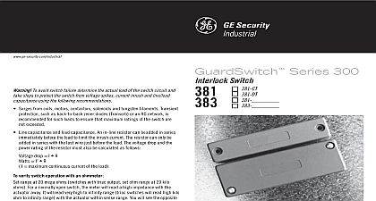
Interlock Switches 300 Series qxd 5 29 08 1 56 PM Page 1 Contacts Switches 301 BT Series 300 DPST safety interlock switch is designed for use with monitored relays or monitored circuits To achieve the optimum Series defeat resistant feature of the 301 BT both the switch circuit Circuit 1 the tamper circuit Circuit 2 must be connected An optional third circuit be provided to indicate at the panel which guard is open Pollution Degree II use of this control device is an essential part of machine cycle control to follow ALL instructions could lead to serious injury or death to be done by qualified personnel only connecting cables between the INT devices and the switches be located in an IP 23 type enclosure minimum mounting for the switch and the actuator magnet must accomplished per this specification hardware must be used for installation housing of the 300 BT must be connected to the Primary Earth ground circuit via a lock washer on mounting screw The PE ground symbol must be adjacent to the screw verify switch operation with an ohmmeter range at 20 mega ohms switches with triac output set ohm at 20 kilo ohms For a normally open switch the meter will a high impedance with the actuator away It will read high kilo to infinity range with the actuator within sense range You will the opposite reading for a normally closed switch 0.57 x 0.24 x 0.61cm Interlock Switch Series Switches 300 Series qxd 5 29 08 1 56 PM Page 2 non removable screws bolts or nuts to mount the switch actuator Do no over torque mounting hardware the switch and actuator so the labels are reading the same direction See Figure 1 the switch on the stationary frame of the machine and the actuator on the moveable guard door or gate the switch and actuator within the listed sense range Ordering Information See Figure 2 for recommended configurations on a ferrous material will effect the sense range minimum of 50 However a non ferrous spacer under the magnet and or switch should restore of the lost sense range best protection against operator defeat mount with screws bolts or nuts See Ordering for details When not used with a Sentrol INT relay particular care be taken to determine the actual load of the switch circuit voltage transients from coils motors contactors and must be considered Transient protection such as zener diodes TransZorb or an RC network is for such loads to ensure that maximum ratings the switch are not exceeded Not recommended to be used tungsten filament loads because of high current inrush surges capacitance and load capacitance must be considered line capacitance can be caused by cable lengths over when using a maximum 48 VAC A resistor can be added in to limit the inrush current at least 48 ohms for 24 Volt The resistor can be added in series just before the load The voltage drop and the power rating of the resistor be considered drop I I3 maximum continuous current of the load mounting the switch on an ungrounded machine ground switch housing by connecting your ground lead to one of the mounting screws Configurations Recommended 2 parallel actuation can result in on off on signal if the actuator by the switch rather than coming to rest in proximity to it is NOT a recommended configuration for safety interlock LED optional LED 1 1 LED 2 2 3 3 shown with magnet actuator away from switch S3 open reed switch closed when actuator within 0.6 open reed switches will close if misaligned tampered with a standard magnet closed reed switch open when actuatior between 0.3 and 0.6 circuit Black and white wires biased tamper circuit Red and blue wires monitor circuit Orange and brown wires face face 1 Switches 300 Series qxd 5 29 08 1 56 PM Page 3 Diagram for Category 3 shown with safety gates guards in closed position Series 300 BT GuardSwitch required for each safety gate 230V AC 120V AC 24V DC Fast or Fuse 5x20 mm F 40mA 80mA 1 4A L2 1 X2 Y1 Y2 Monitor Relay Fast or Slow Fuses 4A 250V mm F Circuit LED on the BLT model will be ON the guard is open 1A 250V DPST GuardSwitches Show with in position all guards The LED of the BLT model will on when the guard is open If guards are open LED will dimmer The maximum number GuardSwitches that can be used 50 although troubleshooting and resistance must be considered not exceed 30 Ohms of combined and line resistance Each will have less than Ohms of resistance VAC VDC VAC VDC Or other DPST GuardSwitch the 300 BT Series installation instructions Diagram for Category 4 shown with safety gate guard in closed position Series 300 BT GuardSwitches with one INT relay are required for each safety gate first applying the INT Safety Monitor Relay the inputs must be cycled to check for proper operation the output contacts close To cycle the inputs the guard must be opened and closed This start up is sufficient however we recommend that the proper operation of the switches and relay be checked least every 24 hours LED on the BLT model will be ON the guard is open 1A 250V 230V AC 120V AC 24V DC Fast or Fuse 5x20 mm F 40mA 80mA 1 4A Fast or 4A 250V mm F L2 1 X2 Y1 Y2 Monitor Relay VAC VDC VAC VDC Or other DPST GuardSwitch the 300 BT Series installation instructions Specifications Range Rating Class Time Circuits Cycles Types O D Folded Stainless Steel to 180 40 to 80 Sealed Contact Switch Encapsulated in Polyurethane 2 4 4X 5 12 12K 66 msec 5.4VA 10 msec 150VA two circuits do not switch simultaneously and depend on the speed of the guard closure on closure speed of 1 per second and a gap of 1 8 a delay of less than 50 msec is typical Under Full Load to 200,000,000 Under Dry Circuit SJTOW K 0.34 0.86cm PVC Jacketed J 0.19 0.48cm PVC Jacketed J 021 0.53cm Switches 300 Series qxd 5 29 08 1 56 PM Page 4 888 378 2329 866 503 3996 519 376 2430 519 376 7258 852 2907 8108 852 2142 5063 61 3 9259 4700 61 3 9259 4799 32 2 725 11 20 32 2 721 86 13 America 305 593 4301 305 593 4300 General Electric Company Rights Reserved Specifications to all models S1 S2 S3 S4 LED D1 N C S5