Edwards Genesis Signal Master Module Installation Sheet

File Preview
Click below to download for free
Click below to download for free
File Data
| Name | edwards-genesis-signal-master-module-installation-sheet-7819253064.pdf |
|---|---|
| Type | |
| Size | 760.95 KB |
| Downloads |
Text Preview
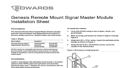
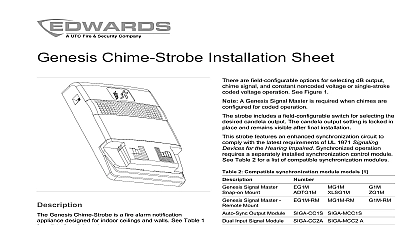
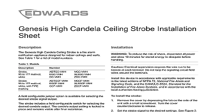
Signal Master Module Installation Sheet Genesis Signal Master Module provides precision and independent horn control for Genesis and horns It mounts on the back of the first appliance the notification appliance circuit Model numbers are listed 1 Models Signal Master 1 ADTG1M EG1M G1M MG1M XLSG1M This module is compatible with Genesis devices For specific and quantities see the compatibility list referenced on the panel Signal Master Module only synchronizes appliances that electrically connected to and electrically downstream from in accordance with applicable requirements in the latest of the NFPA codes and standards and Canadian Code Part 1 Section 32 and in accordance with the authorities having jurisdiction install the module Slide the spade connectors of the Genesis Signal Master into the terminals on the back of the first Genesis on the notification appliance circuit See 1 Observing polarity connect the wires for the remaining under the same terminals as the spade lugs the wiring diagrams Connect the wires to the Genesis Signal Master See 2 through Figure 4 one Genesis Signal Master is required for each appliance circuit strobe input of the Genesis Signal Master requires a NAC whereas the horn input of the Genesis Signal can be cascaded with other Genesis Signal Master on one NAC strobe input source must supply a continuous 24 VDC active determining allowable wire resistance refer to the rating of the Genesis Signal Master Module the appliance and the control panel specifications 1 Mounting the Genesis Signal Master Module Genesis appliance Genesis Signal Master Module 2 Synchronization using one NAC From previous appliance or control panel Genesis appliance with Genesis Signal Master To next appliance EOL resistor or Class A circuit return EOL value is determined by the control panel requirements when using a single horn and strobe NAC circuit the NAC circuit to the bottom two terminals of the Genesis Master Install jumper H to S and H to S as shown shown in alarm condition horns cannot be silenced without turning off the strobes 2013 UTC Fire Security All rights reserved 2 3100124 REV 08 REB 30JAN13 3 Horn silence synchronization using two NACs NAC 1 horn in NAC 1 strobe in Horn resistor value determined by the control panel Genesis appliance with Genesis Signal Master To next appliance EOL resistor or Class A circuit return 4 Horn silence synchronization using one NAC shown in alarm condition horn circuit can be silenced without turning off strobes voltage current rating two to 33 VDC or 16 to 33 VFWR mA A max Actual value limited by system NAC power outputs within 10 ms indefinitely max size environment humidity to 18 AWG 0.75 to 2.50 mm to back of Genesis appliance to 120 0 to 49 to 93 noncondensing information A Division of UTC Fire Security Corporation Inc Town Center Parkway Bradenton FL USA first two digits of the product serial number on the product identification label are year of manufacture 24 DC Regulated 24 FWR 1 1971 compliant Indoor 1971 UL 1638 UL 464 CAN ULC S525 S526 of rating American This module was tested to the regulated 24 VDC FWR operating limits of 16 V and 33 V Do not apply 80 and 110 of these for system operation information contact information see www utcfireandsecurity com Signature data circuit from loop controller or previous device From previous appliance or control panel Genesis appliance with Genesis Signal Master To next appliance EOL resistor or Class A circuit return To next device or Class A circuit return resistor is determined by the control panel requirements shown in alarm condition horn circuit can be silenced without turning off strobes module must be located in the same electrical box as the Signal Master 2 3100124 REV 08 REB 30JAN13