Edwards Hazardous Location Smoke 30-3013A1N12F Install

File Preview
Click below to download for free
Click below to download for free
File Data
| Name | edwards-hazardous-location-smoke-30-3013a1n12f-install-7534680129.pdf |
|---|---|
| Type | |
| Size | 1.45 MB |
| Downloads |
Text Preview
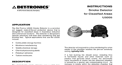
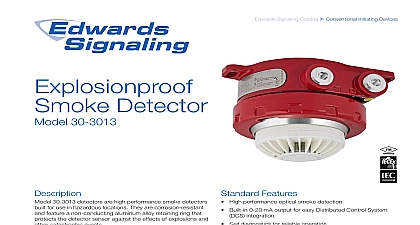
1.0 Rev 12 15 95 8746InstructionsExplosion Proof Smoke Detector30 3013firealarmresources com of Contents 1 1 1 2 3 Warm Up 3 3 Wiring Compartment 4 LED 4 Latching 4 Non Latching 4 Self Test 4 Manual Self Test 4 SAFETY NOTES 5 5 Grease Lubrication 5 of Detector Mounting 5 Protection Against Moisture Damage 6 Supply Requirements 6 Cover 6 Location Options 6 the Detector 7 Cable Requirements 7 7 Procedure 8 9 Routine Inspection 9 REPAIR AND RETURN 13 INFORMATION 13 Spare Parts 13 Accessories 13 30 3013 Model Matrix 13 A FM APPROVAL 14 B IECEx APPROVAL 15 sure to read and understand the entire manual before installing or the smoke detection system Any from the recommendations in this may impair system performance compromise safety 30 3013 Explosion Proof Smoke Detector has and Zone explosion proof ratings and is for industrial and commercial applications detector is designed to operate effectively smoldering and rapidly growing fires and the ability to annunciate fault ensuring no failures The 30 3013 Smoke Detector include 0 20 mA a localized LED and applications that use the 30 3013 include Combustible storage facilities Munitions manufacturing Volatile chemical storage Chemical processing plants Petroleum refineries Turbine enclosures Battery rooms HVAC applications hot swappable sensor module is intrinsically and allows live maintenance while under without de classifying the hazardous area integrated junction box is available in a of port configurations for simplified wiring installation See Figure 1 for all the 30 3013 Detector components Proof Smoke Detector FM Approved for use in Class I Division 1 locations FM Approved for smoke detection performance IECEx Zone approved Trouble free photoelectric operation 0 20 mA output for DCS integration Self checking circuitry ensures reliable smoke Alarm Auxiliary and Fault relays for controlling devices or fire panel interface LED provides a visual indication that an alarm occurred IP44 protection suitable or offshore requirements Ideally suited classified areas oil and gas industry DCS PLC integration with milliamp or relay Rugged design for environmental extremes Visual confirmation of detector alarm Detects smoldering fires No undisclosed failures Electronics Corporation 2015 12 15 SENSOR MODULE RING BOX Components VOLTAGE Vdc 24 Vdc nominal CONSUMPTION watts maximum 2.75 watts at 24 Vdc RELAYS alarm relay Form C 5 amperes at 30 Vdc smoke alarm relay has normally open closed contacts and normally de operation relay Form A 5 amperes at 30 Vdc fault relay has normally open contacts and energized operation relay Form C 5 amperes at 30 Vdc auxiliary relay has normally open normally contacts and normally de energized OUTPUT mA mA dc current with maximum resistance of 300 ohms from 12 17.9 Vdc ohms from 18 to 19.9 Vdc and 600 ohms 20 30 Vdc rated for 14 18 AWG or 2.5 0.75 mm2 wire OPTIONS inch NPT or M25 models available MATERIAL ABS Smoke Detector aluminum painted Junction Box WEIGHT Approximate lbs 3.56 kg PERIOD year RANGE to 65 to 149 to 70 to 158 Figure 2 complete approval details refer to the Appendix RANGE to 95 relative humidity PROTECTION Applicable to ceiling mount only A FM B IECEx smoke alarm relay has a single set of and normally open normally closed and normally de energized operation 19.18 fault relay has a single set of terminals normally open contacts and normally operation auxiliary relay has a single set of terminals normally open normally closed contacts normally de energized operation auxiliary relay functions as pre alarm to 20 mA Output 30 3013 provides a 0 to 20 mA dc current for detector status information to other The circuit is wired in a non isolated and can drive a maximum loop of 300 ohms from 12 to 17.9 Vdc 500 from 18 to 19.9 Vdc and 600 ohms from to 30 Vdc Table 1 defines the current levels corresponding detector status The output calibrated at the factory with no need for field Status Conditions Indicated by Current Level Level mA Status mA mA mA mA mA mA mA Fault Fault up Fault Alarm output of the 0 to 20 mA current loop monitored by the fault detection circuitry the 30 3013 Therefore an open circuit on loop will cause the fault relay to change alarm will normally override a fault unless nature of the fault impairs the ability of detector to generate or maintain an alarm i e loss of operating power 12.67 Dimensions in Inches cm UP the detector is initially powered up a warm period of 1 seconds is allotted for internal and communication During this time the is off and the current level is 3 mA After the are completed normal operation will be by the LED flashing every four seconds level is 4 mA the detector is unable to reach the normal mode the warm up period may extend five seconds followed by a critical fault or an fault see Table 1 for all current levels the problem persists check for any loose wiring ensure that the voltage supply is and cycle power if necessary 30 3013 detector is furnished with smoke fault and auxiliary relays All three relays rated to 5 amperes at 30 Vdc automatically SELF TEST normal operation the detector performs Self Test once per second During the test is not interrupted and no indication is if the test passed If the test fa