Edwards HSL Series Installation Instructions
File Preview
Click below to download for free
Click below to download for free
File Data
| Name | edwards-hsl-series-installation-instructions-0689237154.pdf |
|---|---|
| Type | |
| Size | 1.04 MB |
| Downloads |
Text Preview
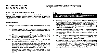
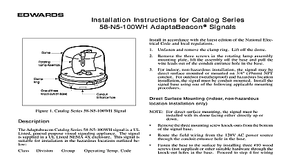
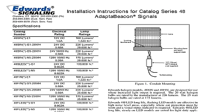
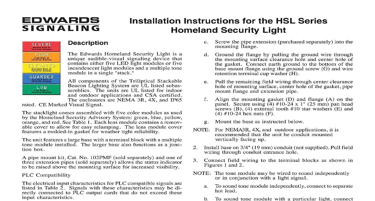
Installation Instructions for the HSL Series Security Light Edwards Homeland Security Light is a audible visual signaling device that either five LED light modules or five light modules and a multiple tone in a single stack components of the Triliptical Stackable Lighting System are UL listed subas The units are UL listed for indoor outdoor applications and CSA certified enclosures are NEMA 3R 4X and IP65 CE Marked Visual Signal stacklight comes assembled with five color modules as used the Homeland Security Advisory System green blue yellow and red See Table 1 Each lens module contains a remov cover to allow for easy relamping The lens module cover a molded in gasket for weather tight reliability unit features a large base with a terminal block with a multiple module installed The larger base also functions as a junc box pipe mount kit Cat No 102PMF sold separately and one of extension pipes sold separately allows the status indicator be raised above the mounting surface for increased visibility Compatibility electrical input characteristics for PLC compatible signals are in Table 2 Signals with these characteristics may be di connected to PLC output cards that do not exceed these characteristics must be in accordance with the latest edition of the Electrical Code and other governing standards and codes standard installation using the 102PMF mounting kit perform the following prevent electrical shock do not connect power instructed to do so prevent abrasion of wiring insulation ensure wire passage holes are adequately protected All references below are to Figure 4 Using the supplied gasket D as a guide mark the four holes and the center clearance hole on an surface the four mounting holes Punch the wiring hole in the mounting surface to be sufficiently than that in the gasket to ensure the wiring is protected from abrasion by the gasket interfering with the mounting screw holes or other appropriate wire insulation abrasion as needed the pipe extension purchased separately into the flange Ground the flange by pulling the ground wire through mounting surface clearance hole and center hole of gasket Connect earth ground to the bottom of the mount flange using the ground screw G and wire terminal cup washer H the remaining field wiring through center clearance of mounting surface center hole of the gasket pipe flange and extension pipe Align the mounting gasket D and flange A on the Secure using 4 10 24 x 1 25 mm pan head B 4 external tooth 10 star washers E and 10 24 hex nuts F Mount the base as instructed below For NEMA3R 4X and outdoor applications it is that the unit be conduit mounted facing up base on 3 4 19 mm conduit not supplied Pull field through conduit entrance hole Connect field wiring to the terminal blocks as shown in 1 and 2 The tone module may be wired to sound independently in conjunction with a light signal To sound tone module independently connect to separate lead To sound tone module with a particular light connect hot terminal to selected light terminal on Cat 102TBS terminal block Apply power to the unit and verify proper operation 1 Wiring Cat No 102TBS NEUTRAL CAT 102TBS BLOCK HOT LEAD OR TO APPROPRIATE MODULE TERMINAL ON 102TBS TERMINAL BLOCK 2 Wiring Cat No 102SIGMT CT 203 699 3300 CUST SERV FAX 203 699 3365 TECH SERV FAX 203 699 3078 3100661 ISSUE 1 2003 Source Replacement Loosen captive screws and remove cover of affected lens Remove the light source assembly from the lens module prevent leakage ensure the magnifier ring on the cover and the magnifier ring on the lens module aligned Figure 3 new light source assembly ensuring that the four prongs the PC board are aligned with the plug located in the back the lens module Replace lens cover and secure using two captive screws lens surfaces should be periodically dusted and cleaned with dry soft clean cloth to maintain optimum light visibility If the outside of the lens may be cleaned with water and a detergent on a well rung out soft clean cloth supplied with base Module Captive Source Key Base No 102TBS shown mm mm 5 8 mm 5 8 mm mm 3 Assembling the Stackable Status Indicator Cat No 102TBS shown for purposes only 3100661 ISSUE 1 o rings 10 24 x 1 25 mm head screws No 102PMF mount flange retention cup washer x 3 8 head thread forming screw tooth Star washer 3100661 ISSUE 1 gasket Hex nut 4 Optional 102PMF Mounting Kit Assembly 1 Specifications Ratings Life hours DC 1.75A AC 0.60A DC 0.05A AC 0.07A No Units Pipe Mount Flange Extension Pipes Assembly Modules Sources shown are for a stackable indicator with 5 light modules lens module color A amber orange B blue C clear G green R red Y yellow lens and LED module color A amber orange B blue G green R red NOTE LED light sources must be used with the color lens module e g a blue LED light source 102LS SLEDB G1 must be used with a blue lens 102LM B For yellow use the 102LS SLEDW light source nominal operating voltage lamp life based on manufacturer calculated lamp life 65 fpm and 50 duty cycle DC 0.32A AC 0.08A DC 0.062A Trade 303 Watts Watts AC 0.022A input DC AC DC AC DC AC No G1 N5 AC volts at 60 Hz 2 PLC Compatibility leakage mA on mA current A ms 3100661 ISSUE 1