Edwards IB4U Analog Isolator Detector Base Installation Sheet

File Preview
Click below to download for free
Click below to download for free
File Data
| Name | edwards-ib4u-analog-isolator-detector-base-installation-sheet-5013824976.pdf |
|---|---|
| Type | |
| Size | 1.21 MB |
| Downloads |
Text Preview
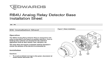
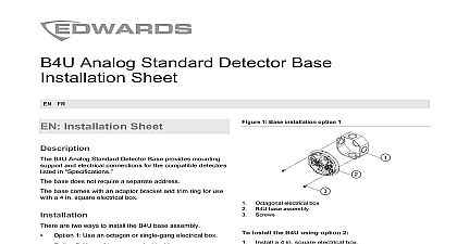
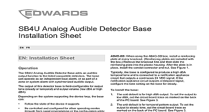
Analog Isolator Detector Base Sheet FR Installation Sheet 1 Base installation IB4U Analog Isolator Detector Base is used to protect a A SLC from total collapse due to wire to wire short This is accomplished by isolating the part of the loop the short from the remainder of the circuit When the of the short circuit is corrected restore the loop by the control panel base does not require a separate address because it the address of the device it is connected to avoid accidental damage to the panel disconnect all before wiring the unit supervision requires the wire run to be broken at terminal Do not loop the signaling circuit field wires the terminals Detector Trim ring Screw Base plate Compatible electrical box install the base a compatible electrical box and then pull all wiring the box Make all wiring connections as shown in below Attach the base plate to the electrical box using the provided with the electrical box Attach the trim ring to the base plate Align the marks on trim ring and base plate press the trim ring onto the plate and the rotate the trim ring until it locks into Attach the desired detector to the base Align the arrows the detector and trim ring press the detector into the and then rotate the detector until it locks into place Apply power and activate the unit to verify that it is properly in accordance with NFPA 72 and CAN ULC S524 Be to observe the polarity of the terminals on the terminal as shown in the diagram the wire run at each terminal Do not loop signaling field wires around terminals Shielded wire is required only in environments with very electrical noise When you use shielded cable follow recommendations connection to and from the base must be and must be insulated from ground Insulate shield using tape Class B wiring there is no shield connection to ground the last device 2013 UTC Fire Security All rights reserved 4 3101076 REV 04 REB 24JAN13 2 Base wiring Fiche D Installation base analogique isolante IB4U pour d est utilis l complet d SLC de classe A en de courts circuits de fil fil On obtient ce r en la partie de la boucle o s produit le court circuit du du circuit Une fois la cause du court circuit corrig on restaurer la boucle en r le panneau base ne requiert pas d s parce qu la m que celle laquelle elle est branch tout dommage accidentel au panneau toute alimentation avant de c dispositif supervision exige que le c soit chaque borne Ne faites pas de boucle des bornes avec les c du champ du circuit de de la base un coffret compatible puis tirez tout le l Effectuez les connexions comme il est indiqu la section Attachez la plaque de la base au coffret l vis fournies avec ce dernier Attachez l de garniture la plaque de la base les marques sur l de garniture avec celles la plaque de la base pressez l dans la plaque faites pivoter l jusqu ce qu se verrouille en Attachez le d d la base Alignez les fl d avec celles de l de garniture pressez d dans la base puis faites le pivoter jusqu ce se verrouille en place Branchez l et actionnez le dispositif pour vous qu fonctionne correctement From previous device To next device size diameter from box including distance from wall mount detectors electrical boxes to 18 AWG wire 0.75 to 2.5 mm 16 and 18 AWG are preferred in 152 mm in 65 mm in 305 mm E PD FX PHD E PHD E HD V PS V PHS V HRD V HFD detectors American 4 inch square x 2 1 2 64 mm deep box American 4 by 4 inch octagonal mud box American 1 7 8 in 47 mm 1 gang box environment humidity temperature range to 120 0 to 49 to 93 noncondensing to 140 to 60 information contact information see our Web site 4 3101076 REV 04 REB 24JAN13 1 Installation de la base 2 Filage de la base D Anneau de garniture Vis Plaque de la base Coffret compatible Du dispositif pr Au dispositif suivant conform aux normes NFPA 72 et Assurez vous de bien observer la polarit des sur le bornier comme indiqu sur le diagramme le filage chacune des bornes Ne faites pas de autour des bornes avec les c du champ du circuit signalisation Le fil prot est exig seulement dans les avec le bruit tr Quand vous le c prot suivez ces recommandations branchement arm la base ou en partant de celle ci continu et isol du sol Isolez le c arm avec ruban magn le filage de classe B il n a pas de connexion arm sol au dernier dispositif technique du c de la base partir du coffret inclus maximale du plafond mural compatibles de 12 18 AWG 0,75 mm2 16 et 18 AWG de mm 6 po cm 65 mm mm 12 po E PD FX PHD E PHD E HD V PS V PHS V HRD V HFD nord am de 10 cm2 po2 x 64 mm 2 po de profond octogonal de 10 cm2 4 po2 bo boue nord am de 47 mm de 49 32 120 93 non condensation 60 140 op relative de la temp obtenir nos coordonn consultez le site Web 3101076 REV 04 REB 24JAN13 4 4 3101076 REV 04 REB 24JAN13