Edwards Installation Instructions, Genesis Outdoor Horn Strobe

File Preview
Click below to download for free
Click below to download for free
File Data
| Name | edwards-installation-instructions-genesis-outdoor-horn-strobe-3867541920.pdf |
|---|---|
| Type | |
| Size | 1.81 MB |
| Downloads |
Text Preview
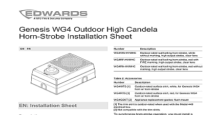
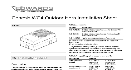
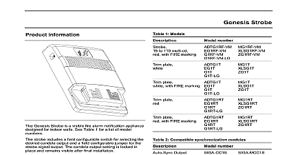
WG4 Outdoor Horn Strobe Sheet FR rated wall ceiling horn strobe white marking clear lens rated wall ceiling horn strobe red with marking clear lens rated wall ceiling horn strobe red without clear lens 2 Accessories 1 Outdoor rated surface skirt white for Genesis WG4 1 or horn strobe surface skirt red for Genesis WG4 or horn strobe Installation Sheet Genesis WG4 Outdoor Horn Strobe is a life safety appliance designed for indoor or outdoor use on or on walls See Table 1 for a list of models and 2 for a list of accessories surface mount applications mount the WG4 onto a Model electrical box using the gasket shipped with the appliance flush mount applications where the mounting surface is with the surface of the wall or ceiling use the WG4GSKT kit that you need a Model 449 electrical box for waterproof or a standard mount 4in square box for all other horn strobe includes field configurable jumper options that you to set the strobe pattern to temporal or continuous horn pattern to temporal or continuous and the horn to low or high The horn strobe also includes a field switch for setting the strobe candela level This is locked in place and is visible after final installation 1 Models WG4WF HVMC Outdoor rated wall ceiling horn strobe white with marking clear lens 2 Appliance replacement gasket flush mount The trim skirt is outdoor rated when used with the Model 449 box Not compatible with the trim skirts synchronize horn strobe operation you must install a synchronization source See Table 3 When the horn strobe to a listed control panel verify operation on the compatibility list for the panel 3 Compatible synchronization source models output signal master mount or auxiliary supply Represents any number of additional characters this device in accordance with applicable requirements in accordance with the local authorities having jurisdiction 2012 UTC Fire Security All rights reserved 10 3102000 ML REV 1.0 ISS 11APR12 Set the horn pattern default horn pattern is temporal To use a continuous pattern cut jumper JP1 See Figure 3 item 5 Connect the signal circuit field wiring to the appropriate noting that both the horn and the strobe are from the same NAC You must observe polarity the unit to function properly See on page 3 Remove the strobe protective cover shown in Figure 3 3 Do not touch the glass of the strobe tube as this may shorten the life of the glass tube Position the cover over the backplate and secure with the Test the unit for proper operation 1 Horn strobe mounting positions 2 Exploded view of the assembly When using a 449 electrical box discard the gasket that is with the box cover screws Electrocution hazard To avoid personal injury or from electrocution remove all sources of power and stored energy to discharge before installing or removing supervision requires that you break the wire run each terminal Do not loop wires around the terminals can mount the Genesis WG4 Outdoor Horn Strobe or vertically on either the wall or ceiling place electrical box accordingly See Figure 1 When using a trim skirt or a surface mount application the gasket that comes with the WG4 unit or flush mount applications on a flat surface use the gasket accessory install the horn strobe Remove the cover from the horn strobe by first removing six cover screws See Figure 2 item 1 Position the appropriate gasket over the backplate that the wire slot and other holes line up properly the protective backing from the gasket surface carefully apply the gasket to the WG4 with the side towards the appliance Press the gasket against the back surface of the appliance so that the seats properly Place the optional trim skirt over the electrical box if See Figure 2 items 4 5 and 6 Also see on page 3 for a list of compatible boxes Feed the field wiring through the wire slots on the gasket the backplate See Figure 2 item 3 and Figure 3 1 Align the appliance and trim skirt if applicable and then the backplate to the electrical box with the supplied Check the assembly to ensure that it is securely Set the candela output default candela setting is D To select a different output align the S2 indicator to the desired output See Figure 3 item 6 For candela output see Table 8 Table 9 and Table 10 Set the strobe pattern default strobe pattern setting is continuous To use temporal strobe private mode which is not ULC cut jumper JP4 See Figure 3 item 4 Set the horn volume default horn volume setting is high To set the horn to volume cut jumper JP3 See Figure 3 item 2 10 3102000 ML REV 1.0 ISS 11APR12 Cover screws 6X Front cover Backplate Optional trim skirt WG4 gasket Electrical box 3 Jumper switch and protective cap locations 5 UL 1971 minimum light output of rating vs angle Wire slot JP3 horn volume jumper Protective cap JP4 strobe pattern jumper JP1 horn pattern jumper S2 candela setting switch Figure 4 Connect all wiring in accordance with national codes and applicable local requirements Equipment hazard To avoid equipment damage that the signal voltage does not exceed the voltage of the device 4 Wiring diagram 10 15 20 Angle Percentage of rated output Horizontal plot not change the factory finish a visual inspection and an operational test twice a or as directed by the local authority having jurisdiction unit is not serviceable or repairable Should the unit fail to contact the supplier for replacement voltage W H D level output tone operating current output size electrical box environment humidity VDC 24 VFWR nominal 8.5 1.4 in 142 216 36 mm Table 4 Table 5 Table 6 and 7 kHz Table 11 Table 8 Table 9 Table 10 and 5 to 18 AWG 0.75 to 2.50 mm 449 in square by 1.5 in deep box to 151 to 66 to 95 noncondensing Horn strobe in Horn strobe in Marking indicates the signal polarity Horn strobe out Horn strobe out Not used to activate the device 3102000 ML REV 1.0 ISS 11APR12 10 4 Sound level output dBA per UL 464 Setting High Low High Low Decibels A weighted 464 Sound level output measured in a reverberant room at 10 ft 5 Sound level output dBA per CAN ULC S525 setting High Low High Lo