Edwards Installation Sheet EG4 Genesis Speaker

File Preview
Click below to download for free
Click below to download for free
File Data
| Name | edwards-installation-sheet-eg4-genesis-speaker-2371458690.pdf |
|---|---|
| Type | |
| Size | 787.98 KB |
| Downloads |
Text Preview
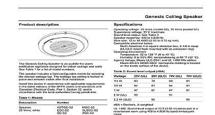
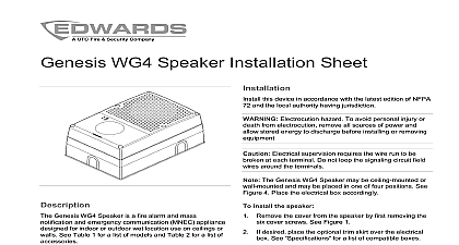
information Genesis Speaker is an audible fire alarm notification designed for indoor walls See Table 1 for a list of numbers speaker includes a field configurable switch for selecting desired wattage tap The wattage tap setting remains after final installation this device in accordance with applicable requirements the latest editions of the NFPA codes and standards Electrical Code Part 1 Section 32 and in with the local authorities having jurisdiction instructions apply to the following model numbers 1 Models Vrms white Vrms white with marking Vrms white Vrms white with marking mount box number Speaker 1 Models mount box number voltage 25 Vrms model S2 70 Vrms model S7 voltage 30 V maximum level output See Table 2 response 400 to 4,000 Hz size 12 to 18 AWG 2.50 to 0.75 sq mm electrical boxes American 4 in square electrical box 2 1 8 in deep listed flush mounted with no extension ring mount box See Table 1 environment 32 to 120 0 to 49 0 to 93 RH noncondensing at 90 32 installation environment Indoor dry listings Meets ULC S541 and UL 1480 fifth edition 2 Sound level output dBA W W W W Decibels A weighted 1480 Sound level output at 10 ft 3.05 m measured in a room using 400 to 4,000 Hz band limited pink Meets or exceeds 85 dBA in an anechoic chamber 10 ft 3.05 m characteristics Within 6 dB of on axis sound level measured 90 off axis horizontal instructions Electrical supervision requires the wire run to be at each terminal Do not loop the signaling circuit field around the terminals install the speaker Remove the cover by depressing the tabs on top of the by inserting a small screwdriver from the top and slightly Connect wires as shown Strobe terminals S and S are used for speaker only devices See the Figure 1 Sheet Speaker P N 3100272 REV 3.0 2 unit is not serviceable or repairable Should the unit fail to contact the supplier for replacement a visual inspection and an operational test twice a or as directed by the local authority having jurisdiction Slide the wattage switch to the desired wattage tap 2 W W 1 2 W or 1 4 W by aligning it with the indicator notch the switch See Figure 2 Mount the unit onto a compatible electrical box See 3 Replace the cover by aligning it at the bottom and it in at the top Test the unit for proper operation voltage matching the voltage rating of speaker 25 or 70 Vrms listed fire control next or end line device S S 1 Wiring diagram switch View notch 2 Wattage switch electrical box mount box 3 Mounting diagram With surface mount box do not install conduit into center knockout Only install conduit into knockouts with plate Verify that the grounding plate provides with conduit 2 3100272 REV 3.0