Edwards Installation Sheet for 105 Series

File Preview
Click below to download for free
Click below to download for free
File Data
| Name | edwards-installation-sheet-for-105-series-0271564389.pdf |
|---|---|
| Type | |
| Size | 814.43 KB |
| Downloads |
Text Preview
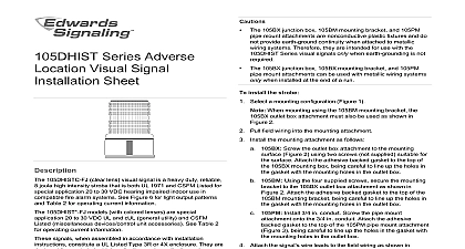
Series Adverse Location Signal Installation Sheet 105 Series visual signals are heavy duty reliable UL cUL utility and CSFM Listed miscellaneous device control unit beacons which when assembled in accordance with instructions constitute a UL Listed Type 4X enclosure and UL Listed for marine use They are designed for use in industrial or in applications where a Type 4X enclosure is required signals are available in steady on halogen flashing halogen joule strobe or 8 joule high intensity strobe assembled in accordance with these instructions the 105 Series signals are UL Listed for use in hazardous locations with temperatures as listed in Table 1 appliances are UL and cUL Listed for use in Class I Division 2 A B C and D Class II Division 2 Groups F and G and Class Division 1 and 2 for hazardous or nonhazardous locations only electrical specifications see Table 2 must be in accordance with local codes The lens should positioned facing up for outdoor applications Explosion hazard Substitution of any component may impair for Class I Division 2 Explosion hazard Do not remove or replace lamps or plug in unless power has been disconnected or the area is to be free of ignitable concentrations of flammable gases or Explosion hazard Do not disconnect while the circuit is live or the area is known to be free of ignitable concentrations To reduce the risks of ignition of hazardous atmospheres and do not apply power to the signal until installation has been and the signal is tightly assembled and secured To prevent electrical shock before starting work on signals the power For strobe models wait 5 minutes for stored to dissipate To avoid risk of injury install the lens before energizing the signal do not remove or insert the light source when the signal is continued Do not disconnect equipment unless power has been removed or area is known to be nonhazardous To reduce the risk of ignition of hazardous atmospheres and keep the assembly tightly closed when circuits are The 105BX outlet box 105BM mounting bracket and 105PM pipe attachments are nonconductive plastic fixtures and do not earth ground continuity when attached to metallic wiring Therefore they are intended for use with the 105XBRi visual signals only when earth grounding is not required The 105BX outlet box 105MB mounting bracket and 105PM pipe attachments can be used with metallic wiring systems only installed at the end of the run install the device Select a mounting configuration Figure 1 When mounting using the 105BM mounting bracket the outlet box attachment must also be used as shown in 2 Pull the field wiring into the mounting attachment the mounting attachment as follows Screw the outlet box attachment to the mounting using two screws not supplied suitable for the Attach the adhesive backed gasket to the top of the outlet box being careful to line up the holes in the with the mounting holes in the outlet box Using the four supplied screws secure the bracket to the 105BX outlet box attachment as in Figure 2 Attach the adhesive backed gasket to the of the 105BM mounting bracket being careful to line up holes in the gasket with the mounting holes in the outlet Install 3 4 in conduit Screw the pipe mount onto the 3 4 in conduit Attach the adhesive gasket to the top of the 105PM pipe mount being careful to line up the holes in the gasket the mounting holes in the outlet box It is not necessary to remove the lens from the strobe base to install the 105HIST Series Mount the 105SINH 105FINH and 105ST Series as follows the gasketed base from the lens assembly as shown in 3 and remove the clear gasket from around the base Secure the base to the appropriate mounting attachment using the screws supplied Replace the clear gasket on the base with flared open end facing down Attach the signal wire leads to the field wiring as shown in Ensuring that the light source is in place screw the lens back on 5 base Mount the 105HIST Series as follows Secure the hi intensity base to the appropriate mounting attachment using the four supplied as shown in Figure 4 Apply power and verify operability 3100290 EN REV 04 ISS 14JAN15 4 1 Mounting configurations 105FINH Series Series 3 105PM pipe mounting on a 105PM mount attachment on a 105BX box attachment on a 105BM bracket with 105BX outlet box tube tube base tube 2 105BM bracket mounting 4 105HIST mounting Series screws mount lens to supplied 4X backed mounting to mount to 105BX 4X backed to mount to the surface 2X Series lens base backed pipe mount in conduit to mount to 105PM 4X series lens strobe backed pipe mount in conduit nipple 4 3100290 EN REV 04 ISS 14JAN15 5 Wiring lens base nuts supplied Shock hazard To prevent electrical shock before starting on signals disconnect the power For strobe models wait minutes for stored energy to dissipate Do not touch the strobe tube or halogen bulb with bare Grasp the light source either by the base or using a soft clean lens should be periodically cleaned using a mild detergent and on a soft clean lint free cloth replace the light source Unscrew the lens from the base For halogen bulb replacement While pressing down on the bulb turn and then pull straight up out of the socket the new halogen bulb into the socket press down and until the bulb is locked into place For strobe tube replacement Grasp the strobe tube by its base and pull straight up out of strobe tube socket Figure 3 Grasp the new strobe tube by the strobe tube base and press the strobe tube socket Screw the lens onto the base Apply power and verify operability 1 Hazardous location ratings Group B C D T3 200 392 G 120 248 120 248 B C D T2A 280 536 G 135 275 135 275 Group 135 275 135 275 B C D T2B 260 500 G B C D T2C 230 446 135 275 G 135 275 B C D T3 200 392 G 120 248 120 248 Lens color A Amber B Blue C Clear G Green Magenta R Red 2 Electrical specifications Steady on Steady on Steady on joule joule joule joule joule joule High High High ratings Current W 226 lumens hours 1 2 W 226 lumens hours 1 2 W 175 lumens hours 1 2 W 226 lumens hours 1 2 W 226 lumens hours 1 2 W 175 lumens hours 1 2 peak hours 3 peak hours 3 peak hours 3 peak