Edwards Installation sheet, Genesis WG4 speaker strobe, high candela

File Preview
Click below to download for free
Click below to download for free
File Data
| Name | edwards-installation-sheet-genesis-wg4-speaker-strobe-high-candela-7392680154.pdf |
|---|---|
| Type | |
| Size | 1.49 MB |
| Downloads |
Text Preview
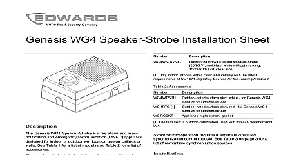
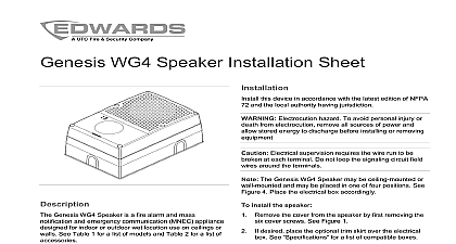
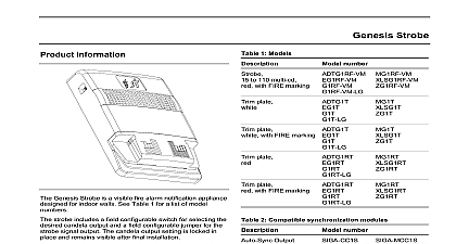
WG4 High Candela Speaker Strobe Sheet wall ceiling speaker strobe V white without marking cd clear lens Only indoor strobes with a clear lens comply with the latest of UL 1971 Signaling Devices for the Hearing Impaired 2 Accessories 1 Outdoor rated surface skirt white for Genesis WG4 1 or speaker strobe surface skirt red for Genesis WG4 or speaker strobe replacement gasket The trim skirt is outdoor rated when used with the 449 weatherproof operation requires a separately installed control module See Table 3 on page 3 for a of compatible synchronization sources this appliance in accordance with the latest edition of 72 and the local authority having jurisdiction Electrocution hazard To avoid personal injury or from electrocution remove all sources of power and stored energy to discharge before installing or removing Electrical supervision requires the wire run to be at each terminal Do not loop the signaling circuit field around the terminals The Genesis WG4 High Candela Speaker Strobe may ceiling mounted or wall mounted and may be placed in one four positions strobe above strobe below and strobe to side place the electrical box accordingly See Figure 4 install the speaker strobe Remove the cover from the speaker strobe by first the six cover screws See Figure 1 on page 2 desired place the optional trim skirt over the electrical See for a list of compatible boxes Genesis WG4 High Candela Speaker Strobe is a fire and mass notification and emergency communication appliance designed for indoor or outdoor wet location on ceilings or walls See Table 1 below for a list of models Table 2 for a list of accessories speaker strobe includes field configurable switches for speaker and strobe output levels The settings are after final installation 1 Models wall ceiling speaker strobe V multi tap red with FIRE marking cd clear lens wall ceiling speaker strobe V multi tap red without marking cd clear lens 1 Outdoor rated wall ceiling speaker clear strobe V multi tap white with ALERT marking cd Amber lens wall ceiling speaker strobe V multi tap white with ALERT marking cd clear lens wall ceiling speaker strobe V multi tap white with FIRE marking cd clear lens 1 Outdoor rated wall ceiling speaker strobe V multi tap white without marking cd amber lens 2011 UTC Fire Security All rights reserved 4 3101853 REV 2.0 ISS 21MAR11 Remove the gasket that comes with the 449 weatherproof 2 Protective cap and replace it with the gasket that comes with the speaker strobe Place the gasket over the backplate and then feed the wiring through the wire slots on the gasket and the See Figure 5 item 3 Secure the backplate to the electrical box with four Connect the wiring to the terminal strip Connect the speaker to the audio NAC and the strobe to strobe NAC Observe polarity See Figure 5 temporal strobe private mode operation is desired cut JP1 See Figure 5 item 5 Set the speaker voltage default speaker voltage is 70 V For 25 V reposition speaker voltage setting switch S3 See Figure 5 4 Protective cap 3 Assembled Set the candela output default candela setting is D To select a different output align the S2 indicator to the desired output See Table 5 and Figure 5 item 1 The default wattage setting is Z corresponding to 1 4 watt select a different wattage align the S1 indicator to the wattage setting See Table 4 and Figure 5 item 2 Remove the strobe protective cover See Figure 2 Position the cover over the backplate and secure with the cover screws Test the unit for proper operation 1 Exploded view of assembly Optional skirt Backplate 4 Mounting positions Front cover Cover screws 6X Cover screws 6X Front cover Backplate Optional skirt Gasket Electrical box 4 3101853 REV 2.0 ISS 21MAR11 5 Wiring JP1 and switch locations A Wire slot S1 wattage setting switch see Table 4 S2 candela setting switch see Table 5 Polarity shown in alarm condition unit is not serviceable or repairable Should the unit fail to contact the supplier for replacement a visual inspection and an operational test twice a or as directed by the local authority having jurisdiction Do not change the factory applied finish VRMS or 70 VRMS switch selectable VRMS VDC 24 VFWR nominal V max Table 4 to 4,000 Hz voltage voltage level output response operating current See Table 8 output size electrical environment humidity 5 Table 6 and Figure 6 to 18 AWG 0.75 to 2.50 mm 449 in square by 1 1 2 in deep box to 151 to 66 to 95 noncondensing V strobe temporal mode selection jumper S3 speaker voltage setting switch UP position is 70 V default position is 25 V 3 Compatible synchronization sources models Output Signal Remote 4 Sound level output dBA W W W W V Decibels A weighted 1480 Sound level output at 10 ft 3.05 m measured in a room using 400 to 4,000 Hz band limited pink noise 5 Indoor strobe output cd 1971 1638 3101853 REV 2.0 ISS 21MAR11 4 6 Outdoor strobe output cd 1638 1638 information 7 UL 1638 outdoor light output cd nominal 65 cd at nominal 52 cd at 8 Strobe operating current in RMS A 6 UL 1971 minimum light output of rating vs angle of manufacture rating American compliance A Division of UTC Fire Security Corporation Inc Town Center Parkway Bradenton FL USA first two digits of the DATE MFG located on the product identification are the year of manufacture 24 DC Regulated 24 FWR UL 1971 requirements 1 UL 1971 1 UL1638 UL1480 NFPA 72 device complies with part 15 of the Rules Operation is subject to the two conditions 1 This device not cause harmful interference and 2 device must accept any interference including interference that may undesired operation Class A digital apparatus complies with ICES 003 Canada Only models with a clear lens meet UL 1971 information contact information see www utcfireandsecurity com 15 10 5 20 25 30 35 40 45 50 55 60 65 70 75 80 85 90 Angle Percentage of rated output Horizontal plot 4 3101853 REV 2.0 ISS 21MAR11