Edwards Integrity Temporal Horn Strobe Installation Sheet

File Preview
Click below to download for free
Click below to download for free
File Data
| Name | edwards-integrity-temporal-horn-strobe-installation-sheet-4867109235.pdf |
|---|---|
| Type | |
| Size | 803.13 KB |
| Downloads |
Text Preview
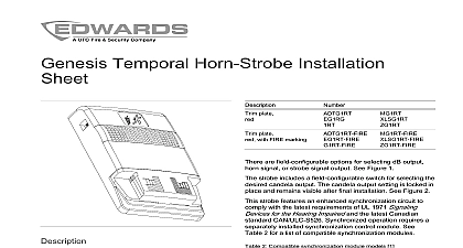
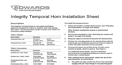
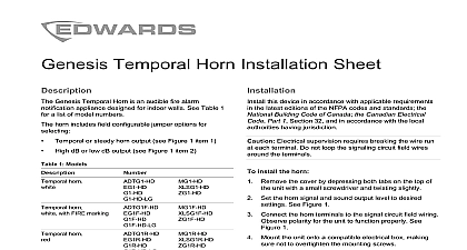
Synchronized Temporal Horn Strobe Sheet Integrity Synchronized Temporal Horn Strobe is a fire notification appliance designed for indoor or outdoor and ceilings The 15 cd strobe is for indoor use only model numbers see Table 1 for accessories see Table 2 1 Models cd horn strobe red 1 cd horn strobe white 1 cd horn strobe red cd horn strobe white cd horn strobe red 2 cd horn strobe white 2 cd horn strobe red cd horn strobe white cd horn strobe red cd horn strobe white For indoor use only Not ULC Listed 2 Accessories box red indoor box white indoor box red box white mounting frame indoor mounting frame indoor strobe operates on any existing two wire signal circuit are jumpers for selecting either a temporal or steady and high or low volume See Figure 4 for the jumper strobe features an enhanced synchronization circuit to with the latest requirements of UL 1971 Signaling for the Hearing Impaired and CAN ULC S526 Visible Devices for Fire Alarm Systems Including Accessories operation requires a separately installed control module See Table 3 for a list of synchronization modules 3 Compatible synchronized models Output Module Signal Master Mount Electrocution hazard To avoid personal injury or from electrocution remove all sources of power and stored energy to discharge before installing or removing supervision requires the wire run to be broken at terminal Do not loop the signaling circuit field wires the terminals ensure flash synchronization do not install this strobe identified by a red cd rating on the front the unit in the same field of view as older models by a black cd rating on the front of the unit this product in accordance with applicable requirements the latest editions of NFPA 72 National Fire Alarm and Code and CSA C22.1 the Canadian Electrical Code 1 Section 32 CAN ULC S524 Installation of Fire Alarm and in accordance with the local authority having 2011 UTC Fire Security All rights reserved 6 3100376 REV 6.0 ISS 06MAY11 1 Mounting diagram in mm in mm in mm in mm in mm in mm in mm in mm in mm in mm Gasket Weatherproof box Standard box Knockouts for 1 2 in 13 mm or 3 4 in 19 mm conduit top Surface mount box Mounting plate supplied 8 32 screw Captive locking screw Hook flange back install the temporal horn strobe Select and install a suitable electrical box See electrical box on page 3 for details Outdoor installations require a weatherproof Set the horn volume and tone See the volume tone on page 3 for details Bring the signal circuit field wiring into the electrical box Position the mounting plate on the electrical box with the flange up and facing outward as shown in Figure 1 the plate using screws provided with the electrical Connect the signal circuit field wiring For the unit to properly observe polarity connect the horn and strobe on the same circuit see 2 To connect the horn and strobe on different see Figure 3 additional wiring details see the installation for the signaling modules or circuits used in fire alarm control panel After completing the connections attach the unit to the plate as noted below The grille has tabs at the top of the inner face that with the hook flange on the mounting plate the bottom of the grille out slightly and slide the into place so that the tabs engage the flange Seat the grille by pressing the bottom in Fasten the bottom of the grille to the mounting plate tightening the captive locking screw Apply power and activate the unit to verify that it is properly 6 3100376 REV 6.0 ISS 06MAY11 2 Typical one circuit wiring diagram 4 Jumper setup and terminal block FOR OUTPUT FOR TONE output tone output continuous Do not change the factory applied finishes unit is shipped from the factory as an assembled unit it no user serviceable parts and should not be a visual inspection and an operational test twice a or as directed by the local authority having jurisdiction voltage operating current See Table 4 operating current See Table 5 output output temporal pattern size electrical temperature outdoor outdoor humidity to 33 VDC 16 to 33 VFWR Table 6 and Table 7 Table 10 s on 0.5 s off 0.5 s on 0.5 s off 0.5 s 1.5 s off repeat cycle to 18 AWG 0.75 to 2.50 mm in 64 mm deep double gang in square box 2 1 8 in 54 mm deep or bidirectional mounting box per 2 to 120 0 to 49 to 150 to 66 to 150 to 66 noncondensing noncondensing is shown in the active state From UL ULC Listed fire alarm control panel signal circuit To next device or end of line resistor for Class B Return to control for Class A connection 3 Typical two circuit wiring diagram is shown in the active state From UL ULC Listed fire alarm control panel signal circuit To next device or end of line resistor for Class B Return to control for Class A connection the electrical box 1 shows mounting details for box When using a 4 in square box use an ring for additional wiring space if needed If a double gang electrical box that is 2 1 2 in mm deep locate the conduit only at the rear of the Weatherproof box Peel off the adhesive backing from the and adhere to the box mount box the volume and tone horn has a jumper for selecting a high or low volume level The default is high volume To set the output to volume remove the output jumper from the circuit board the rear of the unit See Figure 4 below horn has a jumper for selecting either a temporal or steady The default is temporal tone To set the output to steady remove the tone jumper from the circuit board on the rear the unit Save the jumper by sliding it onto a single pin 3100376 REV 6.0 ISS 06MAY11 6 10 Light output cd 1971 1638 cd cd cd cd cd cd indoor wall mount wall ceiling wall ceiling wall ceiling wall ceiling wall ceiling 1 1 1 1 1 Tested at