Edwards R-Series Remote Annunciators and Expanders Installation and Operation Guide

File Preview
Click below to download for free
Click below to download for free
File Data
| Name | edwards-r-series-remote-annunciators-and-expanders-installation-and-operation-guide-4158037962.pdf |
|---|---|
| Type | |
| Size | 982.28 KB |
| Downloads |
Text Preview
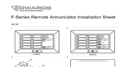
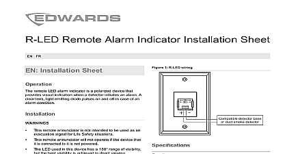
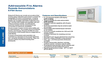
Remote and Installation and Guide 3100969 EN REV 05 ISS 06MAY13 and compliance 2013 UTC Fire Security Americas Corporation Inc R Series Remote Annunciators and Expanders name and logo trademarks of UTC Fire Security Americas Corporation Inc trade names used in this document may be trademarks or trademarks of the manufacturers or vendors of the products A Division of UTC Fire Security Corporation Inc Town Center Parkway Bradenton FL 34202 USA document applies to R Series Remote Annunciators and version 2.0x A This equipment has been tested and found to comply with limits for a Class A digital device pursuant to part 15 of the FCC These limits are designed to provide reasonable protection harmful interference when the equipment is operated in a environment This equipment generates uses and can radio frequency energy and if not installed and used in with the instruction manual may cause harmful to radio communications Operation of this equipment in residential area is likely to cause harmful interference in which the user will be required to correct the interference at his own WEEE directive Products marked with this symbol be disposed of as unsorted municipal waste in the European For proper recycling return this product to your local supplier the purchase of equivalent new equipment or dispose of it at collection points For more information see contact information see www edwardsutcfs com information to the R Series 1 terminals and controls 4 annunciators and expanders 6 diagrams 8 the LCD models 12 the LED models 15 LCD displays 18 Normal screen 18 Message screen 18 screen 19 a password 20 priorities 21 Remote Annunciators and Expanders Installation and Operation Guide Remote Annunciators and Expanders Installation and Operation Guide to the R Series R Series Remote Annunciators and Expanders provide remote annunciation fire and emergency alarm systems The annunciators offer LCD or LED and can include common controls The expander uses LEDs R Series includes three annunciator models and one expander model One two expanders can be connected to any of the annunciator models Figure 1 the four models in the R Series Table 1 lists the features of each model 2 is a complete list of all models and accessories in the series 1 Models in the R Series Fault Enabled Test Fault Enabled Silence Test Fault Enabled Silence Test 1 Features of the models RLCD R RLCDF RLCD CR RLCD CF Yes RLED CR RLED CF No RLED24R annunciators and expanders can be mounted on a standard 4 in square box using the included mounting ring They can also be surface in locking steel enclosures pairs pairs Remote Annunciators and Expanders Installation and Operation Guide annunciators communicate with the FACP on the RS 485 data riser This be configured for Class A or Class B communication The annunciators do provide ground fault isolation annunciators are stand alone units that can be powered by the FACP or by approved power supply with common controls can use a separate remote key switch to enable disable the common controls 2 R Series models and accessories number Annunciator LCD text annunciator without common controls Annunciator LCD text annunciator without common controls Red Annunciator LCD text annunciator without common controls Annunciator LCD text annunciator with common controls Annunciator LCD text annunciator with common controls Red Annunciator LCD text annunciator with common controls Annunciator 16 pair LED zone annunciator with common English Annunciator 16 pair LED zone annunciator with common English Red Annunciator 16 pair LED zone annunciator with common French Expander 24 pair LED zone expander with expander cable and card insert Expander 24 pair LED zone expander with expander cable and card insert Red enclosure for Remote Annunciator enclosure for Remote Annunciator and one Remote including one interconnection cable enclosure for Remote Annunciator and two Remote including two interconnection cables key switch on plate for enabling or disabling common controls card insert for RLED C RLED CR and RLED CF card insert for RLED24 RLED24R Remote Annunciators and Expanders Installation and Operation Guide number box surface mount white single gang expander cable assembly includes cable and hardware expander cable cable only expander cable cable only Remote Annunciators and Expanders Installation and Operation Guide terminals and controls 2 Annunciator rear view showing terminals and controls Mounting slot DIP switch Annunciator bus IN OUT terminals Power riser IN OUT terminals Transmit and receive communication LEDs Remote key switch terminals Expander cable terminals 3 Expander rear view showing terminals Mounting slot Expander cable IN terminals Expander cable OUT terminals Remote Annunciators and Expanders Installation and Operation Guide 3 DIP switch settings to S5 address annunciator address in binary The factory setting is for address 2 Table 4 for examples Possible values 1 to 31 rate 9600 baud factory default setting All other baud rates circuit type Circuit supports Class B and Redundant Class B wiring Circuit supports Class B and Class A wiring used 4 Examples of DIP switch address settings 2 3 4 5 6 7 8 2 3 4 5 6 7 8 2 3 4 5 6 7 8 2 3 4 5 6 7 8 2 3 4 5 6 7 8 2 3 4 5 6 7 8 2 3 4 5 6 7 8 2 3 4 5 6 7 8 2 3 4 5 6 7 8 2 3 4 5 6 7 8 Remote Annunciators and Expanders Installation and Operation Guide annunciators and expanders correct operation the annunciator must be configured with a unique address have the correct baud rate setting and must be in communication with the you are installing a Remote Annunciator and Remote Expanders into RA ENC2 RA ENC3 enclosures you must install the expanders first Refer to the sheets for the enclosures for the correct sequence of steps you are installing Remote Annunciators and Remote Expanders using separate boxes the wire runs between the boxes must be enclosed in conduit you are installing a remote key switch the switch must be located within the or within 3 ft 0.9 m of the enclosure with the cabling installed in or equivalent protection against mechanical injury install an annunciator Secure the mounting ring to the electrical box as shown in Figure 4 Use the DIP switch to set the correct address and baud rate See Table 3 on 5 for DIP switch settings Connect the control panel annunciator circuit to the appropriate annunciator See Figure 5 Figure 6 Figure