Edwards SuperDuct Four-Wire Duct Smoke Detector Technical Bulletin

File Preview
Click below to download for free
Click below to download for free
File Data
| Name | edwards-superduct-four-wire-duct-smoke-detector-technical-bulletin-6435287190.pdf |
|---|---|
| Type | |
| Size | 1.41 MB |
| Downloads |
Text Preview
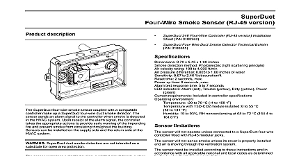
SuperDuct Four Wire Duct Smoke P N 3100685 Rev 2.0 18AUG05 smoke sensor and controller sensor version version 1 documents 2 smoke detector limitations 2 description 2 2 4 4 5 controls and indicators 5 controls and indicators 6 state 6 state 6 state 6 duct detector operation 6 detector installation 7 guidelines 7 guidelines 7 sequence 7 sensor dirty test operation 7 a controller to a sensor in the field 7 tubes 8 the sampling tube from the front of the detector 8 for 36 inch or longer sampling tubes 8 power limited and nonpower limited wiring 8 wiring terminals 9 diagram 9 and service 9 service schedule 9 alarm test 9 dirty test 9 alarm test 10 dirty test 10 station alarm test 10 station sensor dirty test 10 11 the sensor 11 document provides technical information for the SuperDuct four wire duct smoke detector and sensors TSD CJ24 SD CJ ESD SJ TSD 4WJ24 SD 4WJ controller with RJ 45 connectors smoke sensor with RJ 45 connector four wire controller and with RJ 45 modular controller with RJ 45 connectors and cover smoke sensor with RJ 45 connector and cover gasket controller with terminal connectors smoke sensor with block connector sensor with RJ 45 modular and TSD CO2 sensor sensor with terminal block and TSD CO2 sensor TSD CT24 SD CT ESD ST The TSD CO2 module has not been performance to UL 2075 or approved by ULC Bulletin Four Wire Duct Smoke Detector documents addition to this document important information regarding proper installation and maintenance of SuperDuct duct detectors is provided in the following standards NFPA 70 National Electrical Code NFPA 72 National Fire Alarm Code NFPA 90A Installation of Air Conditioning and Systems UL 268A Smoke Detectors for Duct Applications ULC 529 Smoke Detectors for Fire Alarm Systems NEMA Guide for Proper Use of Smoke Detectors in Duct smoke detector limitations duct smoke detectors will not operate without power duct smoke detectors will not operate as designed of the listed electrical and environmental duct smoke detectors will not sense smoke unless ventilation system is operating and the sensor cover is installed duct smoke detectors may not operate as designed the duct detector is installed in accordance with these and all applicable national and local codes as by the local authority having jurisdiction description four wire duct smoke detectors are used to detect under extended temperature ranges in self contained HVAC units such as those typically found on rooftops In self contained commercial HVAC units HVAC equipment is enclosed in a single package to the internal components compressor condensing unit coils etc from adverse environmental conditions or removable service panels provide access to the SuperDuct duct smoke detectors are not intended a substitute for open area protection SuperDuct duct smoke detector see Figure 1 comprises a and one or two sensors Its primary function is to early warning of an impending fire and shut down the unit in order to prevent smoke from circulating the building It is typically used to detect smoke in supply side of the HVAC system but can provide of the return side as well Install supply side sensors at a point downstream from supply fan and air filters and return side sensors at a point the return air is diluted by outside air HVAC unit controller sensor output 1 Duct smoke detector application diagram controller is designed for multiple operating voltages and relay contacts for connection to fire alarm systems controls and other auxiliary functions It can be to a sensor and installed as a single unit or it can be separate from the sensor In installations where the smoke detector controls and indicators are hidden from a remote test reset station can be connected to the to provide these functions In installations using two sensors the duct smoke does not differentiate which sensor signals an alarm trouble condition sensor uses a process called differential sensing to prevent environmental changes from triggering false alarms A change in environmental conditions such as smoke from fire causes the sensor to signal an alarm state but dust and accumulated over time does not When the sensor to compensate for environmental changes has reached limit 100 dirty the sensor signals a trouble condition is introduced to the duct smoke detector sensing through a sampling tube that extends into the HVAC Bulletin Four Wire Duct Smoke Detector and is directed back into the ventilation system through exhaust tube The difference in air pressure between the tubes pulls the sampled air through the sensing chamber a sufficient amount of smoke is detected in the sensing the sensor signals an alarm state and the controller takes the appropriate action to shut down fans blowers change over air handling systems notify the fire control panel etc Excess temperature differentials between the air and the sampled air can produce unwanted inside the sensor which may cause the sensor to improperly Precautions should be taken to limit the range and the amount of condensation to which sensor is exposed description sensor see Figure 2 comprises a plastic housing a circuit board a clear plastic cover an exhaust tube a sampling tube The exhaust tube and sampling tube are d