Edwards SuperDuct Four-Wire Smoke Sensor RJ-45 Version

File Preview
Click below to download for free
Click below to download for free
File Data
| Name | edwards-superduct-four-wire-smoke-sensor-rj-45-version-3420695187.pdf |
|---|---|
| Type | |
| Size | 922.96 KB |
| Downloads |
Text Preview
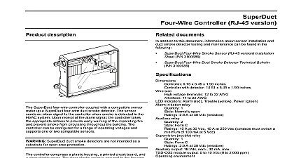
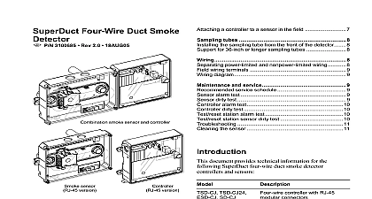
description SuperDuct four wire smoke sensor coupled with a compatible make up a SuperDuct four wire duct smoke detector The sends an alarm signal to the controller when smoke is detected the HVAC system Upon receipt of the alarm signal the controller the appropriate actions to provide early warning of the impending and prevent smoke from circulating throughout the building can be installed on the supply side and the return side of the system SuperDuct duct smoke detectors are not intended as a for open area protection sensor comprises a plastic housing a printed circuit board a clear cover and an exhaust tube The clear plastic cover permits inspections without having to disassemble the sensor The cover to the sensor housing using four captive screws and forms an chamber around the sensing electronics sampling tube is required to introduce air into the sensor The tube is ordered separately and varies in length depending on width of the HVAC duct document provides installation instructions for the following four wire smoke sensors ESD SJ smoke sensor with RJ 45 modular smoke sensor with RJ 45 connector and cover gasket smoke sensor with RJ 45 connector and TSD CO2 module The TSD CO2 module has not been performance evaluated to 2075 or approved by ULC documents addition to this document information about controller installation duct smoke detector testing and maintenance can be found in the Four Wire Controller RJ 45 version Installation Sheet 3100687 Smoke Sensor RJ 45 version 24V Four Wire Controller RJ 45 version Installation P N 3100962 Four Wire Duct Smoke Detector Technical Bulletin 3100685 8.70 x 5.45 x 1.90 inches detection method Photoelectric light scattering principle velocity rating 100 to 4,000 ft min pressure differential 0.005 to 1.00 inches of water 0.67 to 2.46 obscuration ft time 2 seconds max up time 8 seconds max test response time 5 to 7 seconds indicators Alarm red Trouble yellow Dirty yellow Power requirements Included in controller specifications environment 20 to 70 4 to 158 with TSD CO2 module installed 0 to 55 to 131 10 to 93 RH noncondensing at 68 to 72 154.4 to limitations sensor will not operate unless connected to a SuperDuct four wire fitted with RJ 45 modular jacks sensor will not sense smoke unless its cover is properly installed air is moving through the ventilation system sensor must be installed according to these instructions and in with all applicable national and local codes as determined the local authority having jurisdiction sensor must be operated within the specified electrical and limits guidelines the sensor on a flat section of HVAC duct between six and ten widths from any bends or obstructions and not more than 15 ft its controller supply side sensors at a point downstream from the supply fan after the air filter return side sensors at a point before the return air stream is by outside air tubes must extend at least two thirds across the width of the Sampling tubes longer than 36 inches must be supported at both instructions read these instructions thoroughly before installing In addition this document important information can be found in Technical P N 3100685 1 Verify the duct air velocity a small hole at the point where the sensor is being installed Using SD VTK Air Velocity Test Kit and a suitable air velocity meter that the air velocity in the HVAC duct falls within the specified range of the sensor and note which direction the air flows the air velocity does not fall within the specified range relocate the and seal all holes in the HVAC duct Sheet Four Wire Smoke Sensor RJ 45 version P N 3100686 REV 2.0 3 In order to verify airflow direction and velocity air must be through the HVAC system 2 Drill the mounting holes the drill template to the HVAC duct Drill or punch the holes where indicated Remove any rough edges from the 3 Assemble the sensor the sensor as shown in Figure 1 Rotate the air sampling so the inlet holes face the direction of airflow In some applications it may be desirable to install the sampling through the front of the sensor For details refer to Technical P N 3100685 tube tube tube sheet metal screw 2X 2 Sensor installation diagram the sampling tube is longer than the width of the duct drill a 3 4 inch on the opposite side of the duct Extend the sampling tube the hole as shown in Figure 3 and seal all openings outside duct with an approved sealant duct tube tube separately 1 Sensor assembly diagram tubes must extend at least two third across the width of the and must be supported at the far end if longer than 36 inches tubes are available in the lengths listed below sampling tube sampling tube sampling tube sampling tube sampling tube sampling tube sampling tube sampling tube For duct widths greater than 36 inches use a sampling tube that longer than the width of the duct see Figure 3 4 Mount the sensor the sensor to the HVAC duct as shown in Figure 2 Secure the using the two sheet metal screws provided in the hardware kit 36 in 3 Installation with sampling tubes longer than the width of the 5 Verify the air pressure differential the sensor and connect a suitable air pressure differential meter the sampling tube and exhaust tube openings as shown in Figure 4 that the air pressure differential measured between the two falls within the specified operating range of the sensor 3100686 REV 2.0 3 Sheet Four Wire Smoke Sensor RJ 45 version duct tube cable assemblies are available in the lengths listed below wiring harness kit 5 ft wiring harness kit 10 ft wiring harness kit 15 ft If strain relief is required secure the cable assembly using the clamps provided in the cable kit completing the installation test the sensor to ensure that it is correctly before leaving the site For details refer to Bulletin P N 3100685 tube pressure 4 Air pressure differential measurement To measure air pressure differential you must have a suitable pressure differential meter supplied by the installer and an SD Air Velocity Test kit to controller wiring the sensor to the controller as shown in Figure 5 Make sure cable grommets are seated securely into their respective openings cable assembly separately cable assembly separately sensor second sensor 5 Controller to sensor wiring diagram Sheet Four Wire Smoke Sensor RJ 45 version 3100686 REV 2.0 3