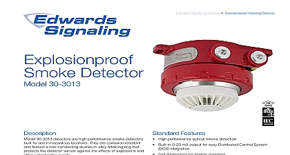
Edwards V9006 Hazardous Location Smoke Detetctor Install

File Preview
Click below to download for free
Click below to download for free
File Data
| Name | edwards-v9006-hazardous-location-smoke-detetctor-install-2306149875.pdf |
|---|---|
| Type | |
| Size | 1.10 MB |
| Downloads |
Text Preview
INSTRUCTIONS Detector Classified Areas Det Tronics U5005 Smoke Detector is a sensitive rugged state of the art protection device that is for classified areas in hazardous industrial commercial locations The detector is designed to effectively with both slow smoldering and fast fires Typical applications that use the U5005 storage facilities manufacturing chemical storage processing plants refineries enclosures photoelectric smoke detector uses a solid state emitting diode IRED and a light sensing cell arranged in a labyrinth assembly The permits free access to smoke but restricts light Because of its critical function to the of the detector each IRED is selected with care and is subjected to rigorous pre production to ensure long term reliability and performance normal operation no smoke the detector the air approximately every four seconds for a of less than one millisecond The photo voltaic cell which is placed at an angle to the pulsed light source is sensitive to the infrared light in specified frequency emitted by the IRED light source is designed to receive a signal only when the pulsed source is activated See Figure 1 smoke enters the chamber the light from the reflects off the smoke particles and reaches the smoke cell When the amount of light by smoke reaches the factory set threshold the smoke alarm circuit is actuated detector will respond to a slow smoldering fire when in the chamber reaches the pre set sensitivity typically 2.3 a fast burning fire should occur including fires flammable liquids and other materials such as that generate black smoke the abnormally movement of smoke into the detection chamber sensed by a special rate compensating circuit An in smoke within the detection chamber that a pre set rate causes the rate compensation to increase the intensity of the light source which detector sensitivity If the smoke continues to at this rate an amplifier circuit is triggered and the generates an alarm If not the detector reverts to sensitivity CELL CHAMBER 1 Section of Sensing Chamber Assembly Electronics Corporation 2010 normally smoky atmospheres the detector will not into alarm as long as the concentration is less than fixed sensitivity of the detector This results in a and positive response with the lowest potential unwanted alarms main enclosure of the detector contains the electronic alarm relay and supervision relay OpERaTION ensure reliable operation the U5005 is equipped with circuitry A regulation photodiode which matched to the smoke detection circuit continuously the output intensity of the IRED and adjusts it as to compensate for an accumulation of dust or contaminants or any other variation that can occur temperature and time A power supervision relay in detector provides a trouble output signal in the event an input power failure RANGE to 140 to 60 to 185 to 85 AND SUPERVISORy RELAy CONTACT ampere at 30 Vdc SPST ALARM RELAy CONTACT RATING amperes at 30 Vdc Form C SPDT bOX material Copper free aluminum Fitting 25 mm female for use in Class I Division 2 A B C and D hazardous detector uses extensive filtering against RF and interference In addition there is a 2 second delay before an alarm is generated Figure 2 printed circuit board inside the detector is coated to the possibility of problems caused by moisture OUTpUTS detector provides a set of Form A SPST NO for connection to the alarm output circuitry a set of SPST NC contacts for supervision of input An auxiliary set of Form C SPDT NO NC alarm contacts is also provided for controlling remote devices alarm output latches on in the event of an alarm an LED located on the outer surface of the housing illuminated to provide a visual indication that an condition has occurred The detector is reset by interrupting input power VOLTAGE to 28 Vdc filtered supply with less than 1.4 vpp at 60 120 Hz CURRENT milliamperes milliamperes pounds 0.91 kilogram U5005 is intended for surface mounting See Figure The mounting screw holes are counterbored for No flat head screws Electrical equipment that is used conjunction with the smoke detector is connected to detector using a terminal strip located in the junction that is furnished with the unit lOCaTION smoke detector is normally mounted on the ceiling not than six inches from a side wall The exact location the detector must be determined by an evaluation on engineering supplemented if by field tests additional information on detector location and contact the National Fire Protection Association Park Quincy Mass 02269 and request a of NFPA Number 72 the Standard on Automatic Detectors 13.5 6.1 INCH DIA 3 36.6 DETECTOR 8.9 2 Dimensions in Inches Centimeters ThE DETECTOR three No 8 flat head screws placed through counterbored holes in the detector flange the detector to the surface location Secure junction box if necessary the cover from the junction box and installation of system conduit Feed the wiring through the remaining junction box or M25 to 3 4 inch adapter Use care not to the wires by twisting them when installing junction box the external wiring to the appropriate and re install the junction box cover See 3 4 and 5 for wiring details CONNECTIONS U5005 contains two sets of relay contacts set of NO Alarm contacts close upon detection smoke set of NC Trouble contacts close when the is powered 2 3 4 5 6 1 2 3 CLOSED SUPERVISORY CONTACTS OPEN ALARM CONTACTS AUXILIARY ALARM CONTACTS SHOWN IN THE NORMAL STANDBY ENERGIZED MODE 3 Terminals 2 3 WIRE B ZONE CONTROL PANEL STUD 4 Detector wiring JUMPER DEVICE BY MANUFACTURER ALARM CONTACTS WIRE B ZONE CONTROL PANEL DETECTOR IN LOOP 2 2 DETECTOR IN LOOP 2 JUMPER 3 3 3 DEVICE BY MANUFACTURER 5 Detector wiring scheduled maintenance normally not however periodic cleaning of the smoke may be necessary when detectors are located abnormally dirty or dusty environments Vacuuming the smoke chamber housing prior to blowing out