EST 85001-0241 — Input Modules

File Preview
Click below to download for free
Click below to download for free
File Data
| Name | est-85001-0241-input-modules-2603948751.pdf |
|---|---|
| Type | |
| Size | 867.95 KB |
| Downloads |
Text Preview
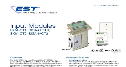
EST Catalog u Intelligent Input Output Modules SIGA CT1HT SIGA MCT2 Notes SIGA CT1 Single Input Module SIGA CT1HT High Tem Single Input Module and SIGA CT2 SIGA MCT2 Dual Modules are intelligent analog addressable devices used to one or two Class B normally open Alarm Supervisory or type dry contact Initiating Device Circuits IDC actual function of these modules is determined by the code selected by the installer This code is downloaded to the from the Signature loop controller during system configura input modules gather analog information from the initiating connected to them and convert it into digital signals module on board microprocessor analyzes the signal and whether or not to input an alarm SIGA CT1 SIGA CT1HT and SIGA CT2 mount to standard American 1 gang electrical boxes making them ideal for lo where only one module is required Separate I O and data connections are made to each module SIGA CT1HT module operates at an expanded temperature of 32 to 158 0 to 70 for those applications more extreme environmental temperature variation SIGA MCT2 is part of the UIO family of plug in Signature modules It functions identically to the SIGA CT2 but advantage of the modular flexibility and easy installation that all UIO modules Two and six module UIO mother are available All wiring connections are made to terminal on the motherboard UIO assemblies may be mounted in enclosures Features Multiple applications Alarm Alarm with delayed latching retard for water applications Supervisory and Monitor The installer selects of four codes to be downloaded to the mod through the loop controller SIGA CT1HT rated for high temperature environments for attic installation and monitoring high temperature detectors Plug in UIO or standard 1 gang mount versions allow quick installation where multiple modules are The 1 gang mount version is ideal for remote loca that require a single module Automatic device mapping modules transmit information to the loop controller their circuit locations with respect to other Signature on the wire loop Electronic addressing addresses are downloaded from the loop con a PC or the SIGA PRO Signature Program Service Tool are no switches or dials to set Stand alone operation module makes decisions and inputs an alarm from initiat devices connected to it even if the loop controller polling stops Function availability dependent upon control Ground fault detection by address ground faults right down to the device level 1 of 4 D A T A S H E E T 85001 0241 to be used for installation purposes Issue 8 Series Overview Signature Series intelligent analog addressable system from Security is an entire family of multi sensor detectors and bases multiple function input and output modules and non network control panels and user friendly main and service tools Analog information from equipment to Signature devices is gathered and converted into signals An onboard microprocessor in each Signature de measures and analyzes the signal and decides whether or not input an alarm The microprocessor in each Signature device four additional benefits Self diagnostics and History Automatic Device Mapping Stand alone Operation and Fast Communication and History Log Each Signature Series constantly runs self checks to provide important mainte information The results of the self check are automatically and permanently stored in its non volatile memory This is accessible for review any time at the control panel or using the SIGA PRO Signature Program Service Tool Device Mapping Signature Data Control SDC learns where each device serial number address is relative to other devices on the circuit The SDC keeps a of all Signature Series devices connected to it The Signature Data Entry Program also uses the mapping feature With menus and graphic support the wired circuits be each device can be examined Layout or drawing showing branch wiring T taps device types and their are stored on disk for printing hard copy SIGA CT1HT and SIGA CT2 modules mount to American 2 inch 64 mm deep 1 gang boxes and 1 inch mm deep 4 inch square boxes with 1 gang covers and SIGA mounting plates The terminals are suited for 12 to 18 AWG mm2 to 0.75 mm2 wire size electrical box plate white ALARM LEDs viewing ports mount the UIO motherboard inside a suitable enclosure with screws and washers provided Plug the into any available position on the motherboard and the module to the motherboard with the captive screws connections are made to the terminals on the motherboard wiring diagram UIO motherboard terminals are suited for 12 18 AWG 2.5 mm2 to 0.75 mm2 wire size 2 of 4 Motherboard UIO Flat washers or electrical enclosure Addressing The loop controller electronically ad each module saving valuable time during system com Setting complicated switches or dials is not required module has its own unique serial number stored in its memory The loop controller identifies each device on loop and assigns a address to each serial number If the modules can be addressed using the SIGA PRO Program Service Tool recommends that this module be installed according to recognized edition of national and local fire alarm codes duty performed by the SIGA CT1 and SIGA CT2 MCT2 is de by their sub type code or Code The code selected by the installer depending upon the desired application is downloaded from the loop controller personality code can be assigned to the SIGA CT1 Two per codes can be assigned to the SIGA CT2 MCT2 Codes 2 3 and 4 can be mixed on SIGA CT2 MCT2 modules only For personality code 1 can be assigned to the first address A and code 4 can be assigned to the second address B ALARM LATCHING Personality Code 1 Assign to one or both circuits Configures either circuit A or B or for Class B normally open dry contact initiating devices such Pull Stations Heat Detectors etc An ALARM signal is sent to loop controller when the input contact is closed The alarm is latched at the module ALARM DELAYED LATCHING Person Code 2 Assign to one or both circuits Configures either A or B or both for Class B normally open dry contact initiat devices such as Waterflow Alarm Switches An ALARM signal sent to the loop controller when the input contact is closed for 16 seconds The alarm condition is latched at the ACTIVE NON LATCHING Personality 3 Assign to one or both circuits Configures either circuit or B or both for Class B normally open dry contact monitoring such as from Fans Dampers Doors etc An ACTIVE signal sent to the loop controller when the input contact is closed The condition is not latched at the module ACTIVE LATCHING Personality Code Assign to one or both circuits Configures either circuit A or or both for Class B normally open dry contact monitoring input as from Supervisory and Tamper Switches An ACTIVE signal sent to the loop controller when the input contact is closed The condition is latched at the module D A T A S H E E T 85001 0241 to be used for installation purposes Issue 8 Wiring will accept 18 AWG 0.75mm2 16 1.0mm2 and 14AWG 1.50mm2 and 12 AWG 2.50mm2 wire sizes Note Sizes 16 AWG 1.0mm2 and 18 AWG 0.75mm2 are preferred for ease of installation See Signature Loop Controller catalog for detailed wiring requirement specifications Slave Device Circuit Wire Specifications Allowable Wire Resistance Allowable Wire Capacitance Design Reference ohms 25 ohms per wire per Circuit per Circuit Distance to EOLR ft 1,219 m Size AWG 0.75 mm AWG 1.00 mm AWG 1.50 mm AWG 1.50 mm SIGA CT1HT 1 Maximum 25 Ohm resistance per wi