ESL 700 Series Install ESL

File Preview
Click below to download for free
Click below to download for free
File Data
| Name | esl-700-series-install-esl-6184932705.pdf |
|---|---|
| Type | |
| Size | 1.05 MB |
| Downloads |
Text Preview
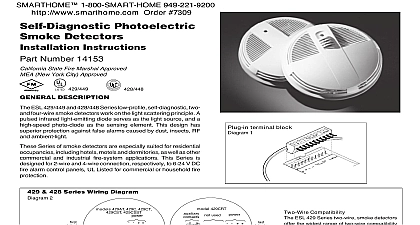
ESL 700 SERIES Self Diagnostic Detectors Instructions ESL 700 Series self diagnostic detectors provide field replaceable chambers and rate of rise heat detectors with fast response in some models 711UT 721UT and 741UT Compatibility two wire units are compatible with a wide range of UL Listed control For information on detector control unit compatibility refer to Compatibility Index For a copy of the Compatibility Index call or visit the Publication Library at www ge security com may not operate if the detector is not connected the control unit initiating device circuit as specified the detector or control unit literature optional four wire operation compatibility listings with individual are not available from UL therefore you only need to verify that voltage range of the detector equals or exceeds the voltage range of control panel power supply and sufficient current is available to the operation of all detectors State Fire Marshal Approved New York City Approved and Spacing the following location guidelines to optimize performance and reduce chance of false alarms Locate ceiling mounted smoke detectors in the center of a room or at least 4 inches 10cm from any walls or partitions Locate wall mounted smoke detectors so the top of the unit is 4 to 12 10 to 30cm below the ceiling See Figure 1 Locate in a suitable environment as follows Temperature between 32 0 and 100 38 Humidity between 0 and 95 non condensing Locate away from air conditioners heating registers and any other source that may interfere with smoke entering the unit Mount units on a firm permanent surface When more than one detector is required spacing of 30 feet 9.1m be used as a guide on smooth ceilings Other spacing may be used on ceiling height high air movement and other conditions response requirements Locate away from kitchens wood stoves garages furnaces and Series 2 Wire Wiring Diagram terminal detail 701U Head Model 711U 702U or 702E all Head Models 702RU 702RE 702U or for Heads Model 731U Test N O Detector Closed Open LED every 9 seconds during normal condition once every second during trouble condition on in alarm indication during loss of power Alarm contacts shown non alarm mode Series 4 Wire Wiring Diagram 741UT Head terminal detail 702U or 702E in Head Detector 702U or 702E in Head Supervision 204 12 24V Detector Alarm contacts shown non alarm mode LED every 9 seconds during normal condition once every second during trouble condition on in alarm indication during loss of power 1 Wiring diagrams 700 Series Alarm Circuit Listed Unit Detector in 100mm here here in 100mm of detector here in 2 Fire sensor placement the Locking Mechanism BEFORE Installation detector head is equipped with a breakaway locking tab slot to prevent removal of the detector head see Figure 3 For installations unauthorized removal of the detector head is not a concern the head be removed by simply turning counterclockwise when the head must lock to the base break away the locking tab with a pair of pliers Then to remove the detector head insert a small into the slot on the side of the base and press in while turning the detector head counterclockwise see Figure 7 the Universal Base 701U and 702U 6 inch diameter universal mounting bases mount to standard single gang electrical boxes 4 inch square round or boxes 3.5 inch octagonal boxes and to WIREMOLD Nos or 5739 fixture boxes The 702E 4 inch diameter universal bases mount only to 3 inch round electrical boxes Bases may be mounted without electrical boxes if approved by the AHJ or if allow 6 inch diameter bases have two parts the base itself that mounts to electrical box or ceiling and the base cover that conceals the screws see Figure 4 The 6 inch diameter bases are shipped coupled to the base cover Mount the base Align the molded line on the base with the base cover twist clockwise to snap in place To remove the base cover simply counter clockwise to unsnap see Figure 4 Pull wire through the electrical box then through the center opening the 700 Series universal base Connect the wire to the appropriate according to the wiring diagrams see Figure 1 Each base is with either three or six clamping type wire terminals and contact springs for contact with detector head circuit pins wire clamping terminal will accommodate two conductors up to mm in diameter 12 AWG Dress the wiring neatly and verify that the continuity switch jumper is touching both terminal 1 and terminal 2 Securely fasten base appropriate hardware see Figure 5 ALL WIRING AND MOUNTING CONNECTIONS Supervision for Four Wire Systems 72 requires power wiring in four wire systems to be supervised This is by installing a power supervision unit for the appropriate unit voltage at the end of the detector power circuit ESL model V power supervision relay recommended for both 12 VDC or VDC operation See 204 V installation instructions for more lock break out tab with pliars 3 Removing the locking tab slot cover slot to head the molded lines on base and cover then to snap into place 4 The 6 diameter mounting base the Wiring for Continuity all universal mounting bases are installed including the end of line check the system wiring for continuity Verify that the manually continuity switch in each base is in the shorting position contact with terminals 1 and 2 for use at initial installation Use a screwdriver to reset any unshorted continuity switches reset prying the jumper wire out of the plastic stopper This establishes across the alarm initiating circuit at initial installation The can now be tested for continuity using an ohmmeter or the Detector Head models 702RE and 702RU have a special plastic protrusion built in to insertion of the wrong heads They are designed specifically for use only 731U heads which include auxiliary relay contacts and are only when high voltage i e 120 VAC is connected to the auxiliary This prevents the installer from inserting a low voltage detector head a base containing damaging high voltages Standard base models 702E 702U can be used with the 731U heads when 120 VAC is not present 700 Series base includes a continuity switch which shorts terminals and 2 together for easy continuity testing When a 700 Series head is the continuity switch will be snapped back out of the way and no longer short terminals 1 and 2 The continuity switch can be back into its original position with a screwdriver if necessary install a detector head insert the head and rotate it clockwise until it is aligned and into the base see Figure 6 Then rotate it an 15 degrees to lock it in place This action will automatically the continuity switch in the base and allow continuity in the to be established by the detector heads