ESL smokes
File Preview
Click below to download for free
Click below to download for free
File Data
| Name | esl-smokes-4075219386.pdf |
|---|---|
| Type | |
| Size | 665.80 KB |
| Downloads |
Text Preview
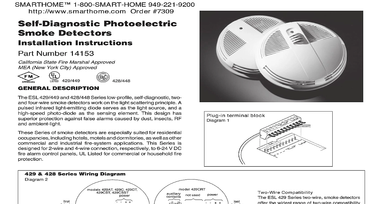
ESL 429 449 428 448 SERIES Photoelectric Detectors Instructions Number 14153 State Fire Marshal Approved New York City Approved 429 449 I S TEDBY A T DESCRIPTION ESL 429 449 and 428 448 Series low profile self diagnostic two four wire smoke detectors work on the light scattering principle A infrared light emitting diode serves as the light source and a photo diode as the sensing element This design has protection against false alarms caused by dust insects RF ambient light Series of smoke detectors are especially suited for residential including hotels motels and dormitories as well as other and industrial fire system applications This Series is for 2 wire and 4 wire connection respectively to 6 24 V DC alarm control panels UL Listed for commercial or household fire 428 Series Wiring Diagram 2 terminal block 1 429AT 429C 429CT 429CSST 429CRT used Compatibility ESL 429 Series two wire smoke detectors the widest range of two wire compatibility the industry Refer to ESL Compatibility for compatible control panel listings OF LINE 448 Series Wiring Diagram 3 449 448 C CT CST CSST 449 448 CSRT CLT CSLT temp output SCLT 448CSH sensor 449 448 non alarm sensor UNIT and 448CSRH are smoke alarms 1 800 SMART HOME 949 221 9200http www smarthome com Order 7309firealarmresources com Features Series includes a wide range of options as shown in the Product Guide Diagram 9 on back page These options include a in sounder an auxiliary relay an integral heat detector and an heat detector to meet almost any application Includes Automatic Testing detector in the Series continually monitors its own sensitivity and status Once a day it performs a full diagnostic test that dynamically testing the sensing chamber and internal elec If a detector drifts out of its UL Listed sensitivity range or fails diagnostics the alarm LED will flash once every second to trouble This meets NFPA 72 field sensitivity testing require without the need for external meters Connect to a power supply that will not automatically reset the self diagnostics only indicate trouble after 27 hours if the supply automatically resets every 24 hours the self diagnostic will never be signaled The smoke detector will still signal correctly Series of detectors mount to standard single gang electrical four inch octagonal or four inch square electrical boxes or on No 5739 fixture boxes These detectors may also be directly to walls or ceilings where local codes jurisdictions pull wire through the electrical box and connect to the plug in block supplied one wire per terminal see Diagrams 1 2 and Second dress wiring neatly and snap the terminal block into the of the detector Note The detector cover must be closed com to support the circuit board while installing the terminal block open the cover and mount the detector using the mounting holes see Diagram 5 ESL smoke detectors are shipped with a plastic dust cover for use areas where construction is on going Smoke detectors will not work the dust cover in place Remove the dust cover when installation completed prior to testing 5 4.70 cm cm instructions on removal terminal block and board call technical at 800 648 7424 switch square or mounting 5739 boxes gang 4 release Positive air pressure from wire openings conduit mounting boxes mounting surfaces or plenums causing air movement through away from the detector may prevent proper operation Seal all causing unwanted air flow using UL Listed expanding foam or Detector Placement and Spacing general ceiling mounted smoke detectors should be located near the of the room or hall whenever possible or more than 4 inches 100 from any wall When the detector is wall mounted the top of the 4 in mm here here in mm of detector here in mm shown are to the edge of the detector Measurements shown are to the closest edge of the detector should be 4 to 12 inches 100 300 mm from the ceiling see 4 Refer to NFPA 72 for further mounting instructions more than one detector is required spacing of 30 feet 9.1 meters be used as a guide on smooth ceilings as defined in NFPA 72 spacing may be used depending on ceiling height high air and other conditions or response requirements Temperature Output Models CLT CSLT Models models have a separate relay output that will be energized when ambient temperature around the detectors falls to approximately Note this detector continues to have the same operating tempera range as standard models 32 0 to 120 50 Run 6 fire wire from a combination burglar fire alarm panel to smoke Connect low temperature relay contact to a separate non fire on a combination burglar fire alarm control panel Warning Do not low temperature output relay to fire alarm zone NOT To Place Detectors of the major causes of nuisance alarms is improper placement of Avoid locating detectors too close to kitchens or wood stoves smoke can be generated Garages and furnace rooms are also locations due to exhaust fumes Placing detectors too close to can cause problems from steamy baths or showers Also do install detectors where normal ambient temperature can be over 37.8 such as attics Refer to NFPA 72 for more information of System Wiring wiring in four wire systems is required by NFPA 72 to be This is accomplished by installing a power supervision relay the end of the detector power circuit The contacts of the supervision are wired in series with the system alarm initiating circuit and are when energized see Diagram 3 A break in the detector power or a loss of power de energizes the power supervision relay the contacts and causing a trouble annunciation at the fire control unit Models 204 6 V and 204 12 24 V are relays UL Listed for 4 wire supervision ESL Model 204 12 24 V CAN is a relay ULC Listed 4 wire power supervision Models 449 448CTE 449CSTE and are smoke detectors with a built in end of line power relay and can be used to supervise a circuit in place of a supervision relay The 449CTE 449CSTE and 449CSSTE will automatically send a trouble signal to the control panel whenever detector needs maintenance Proceed with sensitivity testing on all as outlined on next page 1 800 SMART HOME 949 221 9200http www smarthome com Order 7309firealarmresources com the Installation all connections are complete and the wiring is checked for errors power to the system There should be no alarm If an alarm is determine if a detector is latched in alarm or if there is a problem the wiring smoke detectors shall be tested at least annually in accordance with 72 The preferred method for functional testing is with Smoke in can available from ESL Follow the instructions on the can carefully ensure proper testing Other brands of canned smoke are not due to potential for contamination Other acceptable methods are a smoldering punk stick or a cotton wick detector samples for smoke about every 9 seconds while flashing LED If smoke is detected the sampling increases to every 4.5 Excessive smoke must be detected in three consecutive for the alarm to activate Therefore when testing the detector smoldering punks or cotton wicks hold the smoke source near the entry and gently direct smoke into the detector for 20 seconds until alarm is indicated BE SURE TO PROPERLY EXTINGUIS