Faraday - FireWatch-4000 Fire Alarm Control Data Sheet

File Preview
Click below to download for free
Click below to download for free
File Data
| Name | faraday-firewatch-4000-fire-alarm-control-data-sheet-9576823410.pdf |
|---|---|
| Type | |
| Size | 616.56 KB |
| Downloads |
Text Preview
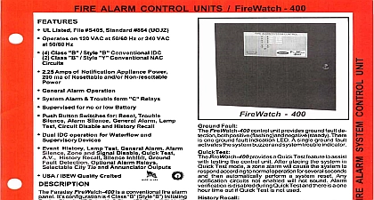
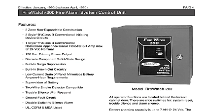
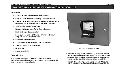
Effective September 27 1999 Replaces January 1998 Fire Alarm Control System UL Listed File S405 Standard 864 Operates on 120 Vac at 50 60 Hz or 240 Vac 50 60 Hz Class Style Conventional IDC expandable to 12 IDC Circuits Class Style Conventional NAC Circuits to 6 Circuits NAC terminals rated up to 12 Awg Amp Power Supply with 2.75 Amps of signal System Relays Optional IDC Alarm Relays Field programmable without special tools Keyed Operator Switch Access Control Serial Drive Annunciator Port Digital Communicator Port Battery Reversal Protection Event History Lamp Test Drill Test Alarm Selectable City Tie Optional Class Adapter Board Made in USA ISO 9001 Quality Crafted Faraday FireWatch 4000 is a conventional modu fire alarm panel It base configuration is 4 Class Style Initiating Device Circuits IDCs with 2 Style Notification Appliance Circuits Expansion modules allow expansion to 12 device circuits and 6 notification appliance for Lamp Test and History Recall operator are enabled by a key switch on the front of panel Without the key for this switch the panel indications but none of the push button operate Settings for 24 hour re sound on silenced trouble conditions Manual alarm silence with 0 1 3 or 6 minute inhibit Auto silence selectable for each NAC 10 20 or 30 or none Test by IDC s or the entire panel Silent or audible Quick Test Local energy shunt or polarity reversal city tie 4000 Fire Alarm Control System and Options Relay board providing a form 1.0A at 30VDC contact from each initiating device circuit Circuits convertible from Class B Style B Y to A Style D Z Optional auxiliary power supply with integral battery charger for additional notification appliance Panel Configuration minimum FireWatch 4000 configuration consists of following components Main logic board Main termination board Transformer Surface Enclosure Cables and hardware basic panel includes 4 Class B Style B initiating circuits All are adaptable to accept smoke manual stations or waterflow switches and contacts All may be programmed for alarm verification with contact closure dis for instant alarm on manual pull station Zone alarms suppress zone trouble indica and each zone may be individually disabled continued 1 LED Annunciator RLC1 P N 12406 FireWatch 4000 panel provides a drive for a annunciator While the remote interface is via drive circuits the physical connection be the panel and the annunciator uses multiplexed data and draws all power from the panel The provides indication of the alarm and trouble of each zone and provides remote silence drill reset capability The connection is supervised Power Supply Unit APS1 P N 12408 auxiliary power supply uses the same basic design the internal power supply but it is packaged in a enclosure The electrical parameters e g voltage battery charging capability system and current are the same as for the main supply Prameters Device Circuits basic FireWatch 4000 panel provides 4 IDC for initiating devices smoke detectors pull stations waterflow sensors and supervisory IDC are Class Style or may be for Class Style in groups of four configured for Class the circuit may be wired or Class Each IDC has a disable switch to the skilled user Operation of this switch a trouble LED in the associated circuit and an alarm condition on that circuit verification is provided and is selectable by IDC enable alarm verification on all IDC set the verify to the position for each IDC Alarm from other zone during verification cycle causes an IDC are Class Style or may be config for Class Style in groups of four When for Class the circuit may be wired Class or Class Fire Alarm Control System minimum panel configuration also includes 2 Class Style Y notification appliance circuits Each is rated 1.5A 24VDC maximum with a total of 3.0A 24VDC Output pattern selectable by circuit to be or coded as march time 60 or 120 BPM or three pulse temporal code one code selection per Auto silence is selectable for each circuit for 10 20 minute 30 minute or no auto silence standard features the minimum configuration panel the following General alarm operation Drill operation Last alarm last supervisory and last trouble Manual alarm silence with 0 1 3 or 6 minute inhibit Recall Lamp Test and Drill Test 24 hour re sound of silenced trouble indications Reset Alarm Silence Trouble Silence General Drivers for a DACT and remote annunciators Complete city tie circuit selectable for reverse polarity alarm trouble signaling local energy or shunt One resettable power output Two non resettable power outputs for auxiliary maximum 75 amps for resettable and outputs combined Four form C status relays for system alarm system system supervisory and power fault Expansion Board ZEB P N 12405 the expanded mode up to two zone expansion extend the main logic display PCB and an termination board must be added to the rear the box for additional field connection zone expansion board also mounts on the panel Up to two zone expansion boards can be used the total number of IDC to 12 and NAC 6 expansion enable board mounts in the rear of the and provides the termination point for the circuits associated with the zone expansion expansion enable board provides connection for up 4 notification appliance circuits and 8 initiating device that are provided by one or two zone expansion An expansion board is only required when a expansion board is used 2 of the base FireWatch 4000 P N 12400 is expandable as follows Verification Fire Alarm Control System Alarms Fault are convertible to a waterflow zone i e it is not The selection of waterflow zone permits IDC to be wired so that sprinkler supervision is in on the same IDC The IDC discriminate circuit alarms as waterflow alarms and tamper as supervisory alarms 12400 panel provides ground fault detection both and negative There is a separate ground indication LED for each A ground fault triggers common fault buzzer and common fault indicator does not interfere with the correct operation of the Supervision Test of the IDC is convertible to sprinkler supervi function with unique indication See Waterflow above Alarm Communicator interface is provided for a digital dialer The wiring the main PCB connector and the digital dialer are not supervised which means that the dialer should be mounted in the 12400 enclo or in an adjacent box A plug in connector is used the panel The dialer can be powered by the 24V filtered power supply from the panel There an off site signaling disable switch that can disable digital dialer outputs 12400 provides a test feature to assist with the panel A quick test is possible in one of two and is selectable on a per zone basis Any of zones may be placed into quick test at the time but only one mode of quick test operation possible for the whole


