Faraday SLU-2 SERIAL ANNUNCIATOR UNIT SLE-16 SERIAL ANNUN EXTENDER

File Preview
Click below to download for free
Click below to download for free
File Data
| Name | faraday-slu-2-serial-annunciator-unit-sle-16-serial-annun-extender-4029315768.pdf |
|---|---|
| Type | |
| Size | 605.51 KB |
| Downloads |
Text Preview
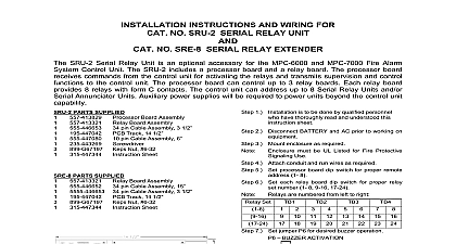
INSTALLATION INSTRUCTIONS AND WIRING FOR NO SLU 2 SERIAL ANNUNCIATOR UNIT NO SLE 16 SERIAL ANNUNCIATOR EXTENDER SLU 2 Annunciator Unit is an optional accessory for the MPC 6000 and MPC 7000 Fire Alarm System Unit The SLU 2 includes a processor board and an annunciator driver board The processor board commands from the control unit for activating the outputs and transmits supervision and control to the control unit The processor board can control up to 4 annunciator driver boards Each board provides 16 supervised outputs for LEDs or incandescent lamps The control unit can address to 8 Serial Relay Units and or Serial Annunciator Units Auxiliary power supplies will be required to units beyond the control unit capability PARTS SUPPLIED Board Assembly Driver Board Assembly pin Cable Assembly 3 1 2 Track 14 1 2 pin Cable Assembly 6 Nut 6 32 Sheet PARTS SUPPLIED Driver Board Assembly pin Cable Assembly 15 pin Cable Assembly 3 1 2 Track 14 1 2 pin Cable Assembly 6 Nut 6 32 Sheet DIMENSIONS DIMENSIONS 1 is to be done by qualified personnel who thoroughly read and understood this sheet 2 Disconnect BATTERY and AC prior to working on 3 Mount enclosure as required must be UL Listed for Fire Protective Use 4 Attach conduit and run wires as required 5 Set processor board dip switch for proper remote 1 8 6 Set jumper P6 for desired buzzer operation BUZZER ACTIVATION REMOTE Processor Board Buzzer 7 Mount PCB Track s using 6 32 keps nuts P N and snap in PCB assemblies 8 Plug cable assembly s PCB as required 9 Connect IN wires from fire alarm system control unit previous remote as required 10 Connect OUT wires to next remote or 120 ohm 140 820350 11 Connect LEDs or lamps as required 12 Apply power to system 13 Program control unit annunciator 14 Check for proper operation of functions Fernwood Road Park New Jersey 07932 315 447345 2 1 OF 2 SLE 16 WIRING Driver Outputs Voltage Range 16 28VDC Current max 0.070A see note 7 Limited Supervised for opens outputs must have a 220K ohm dummy resistor Limited Supervised for power and pair Cable for data X X from panel or previous for power and pair Cable for data X X to next remote or 120 ohm resistor P N 140 on the last remote allows for connection to an regulated and power 24VDC power supply for fire protective use WJ1 when external power used to be installed in accordance with all local codes is not allowed Communication wiring must be daisy chained from unit to unit block will accept a maximum of 12 AWG and minimum of 18 AWG wire twisted pair cable with a characteristic impedance of approximately 120 ohms 4000 feet maximum distance from end to Limited wiring must be kept separate from non power limited wiring minimum following table gives the currents necessary for power supply and battery calculations individual alarm point has a maximum limit of 0.070 A The combined currents of all devices of all SLE 16 modules to this SLU 2 must be less than 0.846 A Current A A Current A Lamp or LED current A Lamp or LED current V nominal V nominal ADDRESS SETTING 1 2 3 ON 4 Used Used Used Used Used Used Used Used SLE 16 HEADER CONNECTIONS SLU 2 Processor Board Output Used Test Switch Silence Switch Acknowledge Silence Switch Reset Switch Buzzer Output open collector Silence Output open collector Output open collector SLU 2 or SLE 16 Driver Board Output 1 2 3 4 5 6 7 8 Used SLU 2 or SLE 16 Driver Board Output 9 10 11 12 13 14 15 16 Used 315 447345 2 2 OF 2