Faraday SRU-2 SERIAL RELAY UNIT SRE-8 SERIAL RELAY EXTENDER

File Preview
Click below to download for free
Click below to download for free
File Data
| Name | faraday-sru-2-serial-relay-unit-sre-8-serial-relay-extender-6283109457.pdf |
|---|---|
| Type | |
| Size | 905.90 KB |
| Downloads |
Text Preview
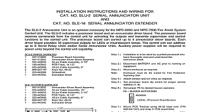
INSTALLATION INSTRUCTIONS AND WIRING FOR NO SRU 2 SERIAL RELAY UNIT NO SRE 8 SERIAL RELAY EXTENDER 1 SRU 2 Serial Relay Unit is an optional accessory for the MPC 6000 and MPC 7000 Fire Alarm Control Unit The SRU 2 includes a processor board and a relay board The processor board commands from the control unit for activating the relays and transmits supervision and control to the control unit The processor board can control up to 3 relay boards Each relay board 8 relays with form C contacts The control unit can address up to 8 Serial Relay Units and or Annunciator Units Auxiliary power supplies will be required to power units beyond the control unit PARTS SUPPLIED PARTS SUPPLIED 34 pin Cable Assembly 3 1 2 Board Assembly Board Assembly pin Cable Assembly 3 1 2 Track 14 1 2 pin Cable Assembly 6 Nut 6 32 Sheet 4 Attach conduit and run wires as required 5 Set processor board dip switch for proper remote is to be done by qualified personnel have thoroughly read and understood this sheet 7 Set jumper P6 for desired buzzer operation must be UL Listed for Fire Protective Use 3 Mount enclosure as required number 1 8 9 16 17 24 are numbered from left to right 6 Set each relay board dip switch for proper relay 2 Disconnect BATTERY and AC prior to working on Track 14 1 2 Nut 6 32 Sheet Board Assembly pin Cable Assembly 15 BUZZER ACTIVATION Set 1 8 DIMENSIONS DIMENSIONS REMOTE Processor Board Buzzer 8 Mount PCB Track s using 6 32 keps nuts P N and snap in PCB assemblies 9 Plug cable assembly s PCB as required 10 Connect ground wire s to chassis ground using keps nut s P N 899 G67197 11 Connect IN wires from fire alarm system control or previous remote as required 12 Connect OUT wires to next remote or 120 ohm resistor P N 140 820350 13 Connect relay contacts as required 14 Apply power to system 15 Program control unit for required relay operation 16 Check for proper operation of functions 315 447344 2 1 OF 2 SRE 8 WIRING Limited Supervised for power and pair Cable for data X X from panel or previous for power and pair Cable for data X X to next remote or 120 ohm resistor P N 140 on the last remote allows for connection to an regulated and power 24VDC power supply for fire protective signaling jumper WJ1 when external is used Contacts in normal standby condition max Resistive Power Limited Source Unsupervised to be installed in accordance with all local codes is not allowed Communication wiring must be daisy chained from unit to unit block will accept a maximum of 12 AWG wiring and minimum of 18 AWG twisted pair cable with a characteristic impedance of approximately 120 ohms 4000 feet maximum distance from end end Limited wiring must be kept separate from non power limited wiring minimum following table gives the currents necessary for power supply and battery calculations Current A A Current A All relays activated A All relays activated V nominal V nominal ON ADDRESS SETTING 1 2 3 4 Used Used Used Used Used Used Used Used BOARD HEADER CONNECTIONS Processor Board Output Used Test Switch Silence Switch Acknowledge Silence Switch Reset Switch Buzzer Output open collector Silence Output open collector Output open collector 315 447344 2 2 OF 2