Fike Chime and Chime Strobe P 1 57 01

File Preview
Click below to download for free
Click below to download for free
File Data
| Name | fike-chime-and-chime-strobe-p-1-57-01-5706249381.pdf |
|---|---|
| Type | |
| Size | 706.57 KB |
| Downloads |
Text Preview
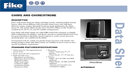
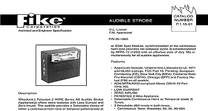
CHIME AND CHIME STROBE wall mount electronic chime and chime strobe manufactured by System offer sixteen different field selectable chime tones each with three volume settings Intended for private mode applications the chime UL 464 and the chime strobe meets UL1971 Chime strobe models are in 15 15 75 75 and 110 candela configurations chime and chime strobe also offer DIP switch tone selections to simplify configuration In addition each device mounts to standard depth back boxes greater installation flexibility Small footprint or surface mount accessory plates are available for the chime with the stylish low profile design consistent with all Fike wall products chime and chime strobe are available in red or white to meet installation requirements FEATURES SPECIFICATIONS Chime meets UL 464 requirements for Mounting Chime Sounder mode Strobe meets UL 1971 requirements Field selectable tones Repeating 1 second chime Repeating 1 4second chime Temporal 3 chime Single stroke chime Continuous 3kHz Continuous 500 Hz Temporal 3 3kHz Temporal 3 500 Hz Three volume options Mount to standard back boxes Available in red or white Input Terminals 12 to 18 AWG Dimensions Chime with mounting plate 5 x 5 8 x 2 1 4 Chime Strobe 6 15 16 x 5 x 2 7 16 Operating Temperature 32 to 120 to 49 Weight Chime 0.5 lb 0.2 kg Chime Strobe 1.5 lbs 0.6 kg Current Draw Chime Single gang 4 x 4 box Chime Strobe 4 x 4 back box Voltages Chime 12 or 24 VDC and FWR Chime Strobe 24 VDC and FWR be powered with a non power supply Operating Voltage Range Chime 8 Chime Strobe 16 33V Sound Output UL Reverberant 12VDC 54 dBA 24VDC 60 dBA Electronic Chime Current Draw 10 CSFM 7135 1209 206 7135 MEA Approved 397 00 E 291 UL S4011 Factory default settings 1.0K repeating 1 chime high volume shown to installation manual for sound levels at each tone selection Average chime current draw varies tones selected Current ratings per System testing at 12VDC and 24VDC Add values when connecting in parallel No Operating mA RMS Operating RMS Operating Horn RMS Operating Horn RMS S 10th Street P O Box 610 Blue Springs Missouri 64013 0610 U S A 816 229 3405 816 229 0314 www fike com MODELS Model No Model No Box Skirt Footprint Plate Box Skirt Mounting Replacement AND ENGINEERING SPECIFICATIONS chime and chime strobe shall be a System Sensor model The chime shall be listed to UL 464 fire protective signaling systems and shall perform in accordance with private mode emergency and general utility The strobe shall be listed to UL1971 and shall be approved for fire protective signaling The strobe shall comply the Americans with Disabilities Act requirements for visible signaling appliances flashing at 1 Hz over the strobe voltage range The strobe light shall consist of a xenon flash tube and associated lens reflector system The chime have sixteen field selectable tone options each with three volume settings These options shall be activated through the settings on a DIP switch located on the rear of the unit The chime shall be capable of mounting to a standard x 4 or 1 1 2 back box or a single gang 2 x 4 1 7 8 back box The chime strobe shall be capable of mounting to a 4 x 4 or 1 1 2 back box The chime shall operate at 12 or 24 volts and the chime strobe shall operate at 24 Both chime and chime strobe shall be powered from a non coded power supply and shall be capable of operating either a regulated DC or full wave rectified unfiltered power supply Chime and chime strobe shall have an operating range of 32 to 120 Fike Corporation All Rights Reserved No P 1.57.01 May 2004 Specifications are subject to change without notice