Fike Duct detector

File Preview
Click below to download for free
Click below to download for free
File Data
| Name | fike-duct-detector-0516237489.pdf |
|---|---|
| Type | |
| Size | 642.91 KB |
| Downloads |
Text Preview
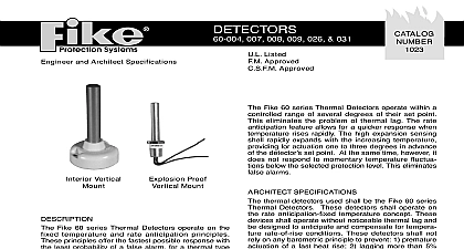
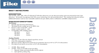
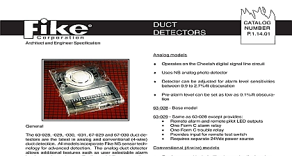
Architect and Engineer Specification models of Duct Detectors Photoelectric 63 023 and 67 022 are offered for use with our control pan These units provide detection of smoke and combus product moving through an HVAC duct The detectors a 4 wire configuration for power and annunciation and Alarm contacts allow the control panel to monitor of the duct detector the duct detector housing a convenient twist in twist detector head design offers easy removal of detector quick cleaning and maintenance This also allows for in changing the detector type without removing the housing A transparent cover makes it easy to visually the units for proper operating status and cleanli unit utilizes a streamlined housing that measures just deep Exhaust tubes are molded into the housing to help installation The detector can be used in conjunction the building HVAC system to facilitate the shutdown fans and blowers and to change over air handling sys so toxic smoke is not spread throughout the facility 24 VAC DC or 120 220 VAC operation Photo and Ionization Detectors Rated for 500 to 4000 FPM Air Velocity Two Form C Contacts Clear Polycarbonate Cover for Convenient Visual Remote Test Station Option Easy Mounting to Round or Rectangle Duct for 1 to 12 Wide Manufacturer Listings U L U L C F M CSFM MEA MODULE MODULE MODULE MODULE MODULE DETECTOR 67 022 unit allows for testing by several quick and easy meth The detector can be placed into an alarm condition the magnet test rod or test card The latched alarm can be reset at the system control panel or at the recessed test switch on the Ionization and Photoelec detectors can be operated by inserting an object of 0.1 diameter into the recessed switch When the is activated the LED on the detector will light within seconds to indicate the detector is in alarm The built in functions are designed to simulate a 3 per foot ob level on the ionization units and a 4 per foot on the Photoelectric detector If a more precise is required for the Photoelectric detector then a cali test card can be used A special slot in the screen allows the test card to be inserted into the cham detector sensitivity can be tested using the interface 02 3727 This device supplies an interface between standard DC voltmeter or multimeter and the detector coiled cord plugs directly into the powered detector to for easy monitoring sensor chamber requires routine maintenance A cleaner and or clean compressed air will restore area and the cover to a new condition Water other fluids should not be applied to the sensing cham The detector sensitivity tester should be used semian Supply VDC VAC 50 60 Hertz VAC 50 60 Hertz VAC 50 60 Hertz Power from plus Signal Terminals 5 6 and 7 Current mA mA AC avg mA AC avg mA AC avg Alarm 95 mA 155 mA AC avg 55 mA AC avg 30 mA AC avg mA 150 mA 1999 Issue S 10th St P O Box 610 Blue Springs MO 64013 0610 U S A 816 229 3405 Fax 816 229 4615 E mail fpssales fike com Rating Initiation contacts Auxiliary contacts VAC DC 0.6 power factor 30 VDC 277 VAC 0.75 power factor 240VAC 0.4 power factor HP 120 VAC HP 240 VAC 32 VDC resistive Information Detectors 4 Wire Ionization Duct Detector 4 Wire Photoelectric Detector Sampling Tubes Duct Widths 1 2 Duct Widths 2 4 Duct Widths 4 8 Duct Widths 8 12 and Maintain Equipment Contacts Temperature Humidity duct Velocity inches 37cm inches 13 cm inches 10 cm lbs 1.8 kg to 49o C 32o to 120o F to 93 to 4000 ft min Detector Sensitivity Interface Module Multimeter Test Card Photoelectric POWER INPUTS AUXILIARY CONTACTS FAN SHUTDOWN ETC C N O C N C AUXILIARY CONTACTS SHOWN IN CONTACTS TRANSFER DURING AS INDICATED BY THE ARROWS ALARM SIGNAL AUX POWER AUX POWER INTIATION CONTACTS POWER TO TERMINALS POWER INPUTS POWER INPUTS IS REQUIRED EACH DUCT DETECTOR ALL FIELD TO THE TERMINALS AUXILIARY CONTACTS FAN SHUTDOWN ETC AUXILIARY CONTACTS FAN SHUTDOWN ETC C C AUXILIARY CONTACTS SHOWN IN CONTACTS TRANSFER DURING AS INDICATED BY THE ARROWS AUXILIARY CONTACTS SHOWN IN CONTACTS TRANSFER DURING AS INDICATED BY THE ARROWS CONTACTS CONTACTS INTIATION CONTACTS INTIATION CONTACTS LISTED PANEL MODULE BY PANEL FOR PROPER SUPERVISION THE WIRES SHOULD BE BROKE AT EACH TERMINAL AND NOT LOOPED AROUND NO D1102 1999 by Fike Corporation All rights reserved PRINTED IN U S A