Fike Gangable Sync Control Modules P 1 26 01

File Preview
Click below to download for free
Click below to download for free
File Data
| Name | fike-gangable-sync-control-modules-p-1-26-01-0539164728.pdf |
|---|---|
| Type | |
| Size | 783.55 KB |
| Downloads |
Text Preview
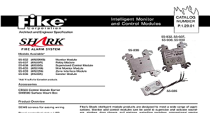
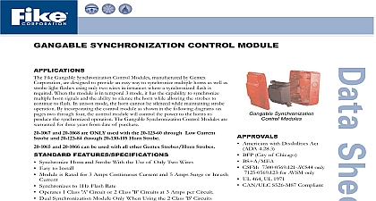
GGAANNGGAABBLLEE SSYYNNCCHHRROONNIIZZAATTIIOONN MMOODDUULLEE Fike Gangable Synchronization Control Modules manufactured by Gentex are designed to provide an easy way to synchronize multiple horns as well as light flashes using only two wires in instances where a synchronized flash is When the module is in temporal 3 mode it has the capability to synchronize horn signals and the ability to silence the horn while allowing the strobes to to flash In unison mode the horn cannot be silenced while maintaining strobe By incorporating the control module as shown in the following diagrams on two through four the control module will control the power to the horns to the synchronized operation The Gangable Synchronization Control Modules are for three years from date of purchase and 20 1068 are ONLY used with the 20 123 60 through Low Current and 20 123 84 through 20 130 105 Horn Strobe and 20 1066 can be used with all other Gentex Strobes Horn Strobes FEATURES SPECIFICATIONS Synchronize Horn and Strobe With the Use of Only Two Wires Easy to Install Module is Rated for 3 Amps Continuous Current and 5 Amps Surge or Inrush Synchronizes to 1Hz Flash Rate Operates 1 Class Circuit or 2 Class Circuits at 3 Amps per Circuit Dual Synchronization Module Only When Using the 2 Class Circuits A Green LED Status Indicator to Signal Operation of Module Option to Silence the Horn While Strobes Continue to Flash When Using 3 Mode Sync Control Modules come with back box and cover plate Dimensions Module 3.85 H x 3.82 W x 1.32 D Box 5.57 H x 4.55 W x Three Year Warranty From Date of Purchase Available in Red or White MODELS Synchronization Modules Americans with Disabilities Act 4.28.3 BFP City of Chicago BS A MEA CSFM 7300 0569 121 AVS44 only AVSM only UL 464 UL 1971 CAN ULC S526 M87 Compliant A green LED status indicator flash once every four seconds if zone is operational If zones one and two operational the LED will flash twice four seconds P N P N Operating mA mA Synchronization Control Red Synchronization Control White Synchronization Control for use with Low Current Strobes Red Synchronization Control for use with Low Current Strobes White S 10th Street P O Box 610 Blue Springs Missouri 64013 0610 U S A 816 229 3405 816 229 0314 www fike com Diagram 1 One Class B Circuit with Strobe Horn Operating in Unison Diagram 2 Two Class B Circuits with Strobe Horn Operating in Unison Diagram 3 Wiring for One Class B Circuit with Strobe Horn Operating Independently Diagram 4 One Class A Circuit with Strobe Horn Operating in Unison Diagram 5 One Class A Circuit with Strobe Horn Operating Independently Diagram 6a One Class B Circuit with Strobe Horn Operating in Unison and Use of Slave Module Diagram 6b One Class B Circuit with Strobe Horn Operating Independently and Use of Slave Module Diagram 7 One Class A Circuit with Strobe Horn Operating Independently and Use of Slave Module top two terminals If power runs are made to the signal one for the strobe and one for the horn only one of When using the Commander 2 3 and 4 Series incoming positive power lead must be broken and each lead is to be inserted into of runs must its positive lead broken and placed under the two separate top terminals A barrier is provided to prevent both leads from being placed under same terminal Low Current Modules are listed per UL 1971 Signaling Appliances for the Hearing Impaired with a voltage range of 8 33VDC FWR CAN ULC S526 M87 Visual Signaling Appliances with a voltage range of 10VDC FWR to 30VDC FWR 20 10 It is indoor use only with a temperature range of 0o 49oC 32o 120oF and a maximum humidity of 93 RH The Low Current Modules are to be connected only to circuits that provide continuously applied voltage Do not use this module coded or interrupted circuits in which the voltage is cycled on and off Fike Corporation All Rights Reserved No P 1.26.01 1 2 May 2004 Specifications are subject to change without notice