Fike HFC-227EA Pre-Engineered Nozzles C 1 02 01

File Preview
Click below to download for free
Click below to download for free
File Data
| Name | fike-hfc-227ea-pre-engineered-nozzles-c-1-02-01-1754260983.pdf |
|---|---|
| Type | |
| Size | 714.55 KB |
| Downloads |
Text Preview
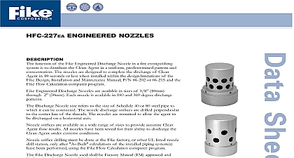
HFC 227EA PRE ENGINEERED NOZZLES function of the Fike Nozzle in a fire suppression system is to distribute the Agent in a uniform predetermined pattern and concentration The nozzles designed to complete the discharge of Clean Agent in 10 seconds or less installed within the design limitations of the Fike Design Manual P N 06 or 06 215 Nozzles are available in five sizes Each nozzle comes in two configurations 180 and 360 degree distribution patterns PRE ENGINEERED NOZZLES NUMBER 10mm 15mm 25mm 40mm 50mm PRE ENGINEERED NOZZLES NUMBER 25mm 40mm 50mm AND ENGINEERING SPECIFICATIONS Nozzle used to distribute the Clean Agent shall be a Fike Series 80 The nozzle shall be available in 3 8 10 mm 15mm 1 25mm 1 1 2 40mm and 2 50mm sizes Each nozzle is available in two styles 180 and 360 degree patterns The nozzle used shall be provided with internal pipe threads that correspond to the nozzle size The used shall be Underwriters Laboratories listed and Factory Mutual approved See diagrams on next page for nozzle coverage The Fike Nozzle is provided with pipe threads that correspond to the nozzle size With this the Fike Nozzle can be installed directly at the Clean Agent container or remotely at the end of a discharge system Pre Engineered Nozzles UL Listed Ex 4623 ULC Listed CEx624 FM Approved 0Y4A8 AF No C 1.02.01 3 S 10th Street P O Box 610 Blue Springs Missouri 64013 0610 U S A 816 229 3405 816 229 4615 www fike com Size and Area Coverage Nozzle Nozzle Area Coverage Type English Metric Height English Height Metric in to 16 ft in to 16 ft to 4.88m to 4.88m An allowable area of coverage includes any area where the maximum coverage from the nozzle R dimension is not exceeded Nozzles should be located on center line of hazard area When working with ceiling heights exceeding the values tabulated above the hazard volume must be broken down into vertically stacked hazard with heights less than the maximums shown in the table It is imperative that unusual applications of this nature be handled by experienced in the field and in most cases operational tests should be performed before the system is put into service Dimensions and nozzle data shown are taken from the UL listed and FM approved Design Installation Maintenance Manual P N 06 180 and 360 degree nozzles may be placed a maximum of 1 foot 30.5cm down from the ceiling and 180 degree nozzles may be placed a or 06 215 of 1 foot 30.5cm from the wall Fike Corporation All Rights Reserved No C 1.02.01 3 March 2005 Specifications are subject to change without notice