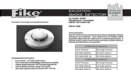
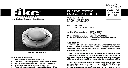
Fike Ionization Smoke Detector P 1 17 01

File Preview
Click below to download for free
Click below to download for free
File Data
| Name | fike-ionization-smoke-detector-p-1-17-01-2184603957.pdf |
|---|---|
| Type | |
| Size | 752.61 KB |
| Downloads |
Text Preview
Architect and Engineer Specification FEATURES profile 1.8 high with base or 4 wire base compatibility relay bases available stable operation RF Transient protection standby current 40 at 24 VDC built in power alarm LEDs for 360 viewing smoke chamber resistant security locking feature magnetic detector sensitivity test feature Meets 72 Chapter 7 Inspection Testing and Mainte requirements with Fike 63 1024 photoelectric detector compatible with Fike 63 1008 and 67 1016 detectors Source Voltage Voltage Voltage Current Current Current Temperature 0.5 30.0 VDC 33.0 VDC VDC 24 VDC max 24 VDC max 24 VDC to 120 to 49 Case Material Bone PC ABS Blend Test Feature Magnetically activated reed switch test DETECTOR Listed S4021 Approval 3010873 7271 0410 135 67 1033 67 1033 can be used in all areas where Ionization Smoke are required The responsive yet highly stable allows the 67 1033 to fit in a wide range of uses It be used in areas where early warning of superheated or combustibles is expected 67 1033 ionization smoke detector utilizes two bi colored for status indication purposes In a normal standby the LEDs flash green approximately once each When the detector senses smoke and goes into the status LEDs will latch on red single radioactive source of Americium 241 ionizes two within the detector a reference chamber and the sensing chamber The air is ionized by this source a small DC current flows between the electrodes of each Smoke can freely enter the sensing chamber while inner chamber is virtually sealed to smoke Smoke the sensing chamber causes a reduction in the DC flow the voltage imbalance between the two chambers proportional to the smoke density When the voltage become great enough it causes the detector to into alarm The two chamber design is utilized to for changes in atmospheric and environmental 2003 Issue S 10th Street P O Box 610 cid 127 Blue Springs Missouri 64013 0610 U S A cid 127 816 229 3405 cid 127 Fax 816 229 0314 cid 127 www fike com SPECIFICATIONS contractor shall furnish and install where indicated on the plans the 67 1033 ionization smoke detectors The combi detector head and twist lock base shall be UL listed compatible with a UL listed fire alarm panel base shall permit direct interchange with 63 1024 photoelectric type smoke detector the 63 1025 combination photo detector and or 60 1029 or 60 1030 fixed temperature rate of rise heat detectors The base shall be a listed twistlock base In the event of partial or complete retrofit the 67 1033 may be used in conjunction with or as replacement for Fike detectors 63 1007 63 1016 and the 67 1016 smoke detector shall have two flashing status LEDs for visual supervision When the detector is in standby condition LEDs will flash Green When the detector is actuated the flashing LEDs will latch on Red The detector may be reset actuating the control panel reset switch sensitivity of the detector shall be capable of being verified It shall be possible to perform a functional test of the without the need of generating smoke The test method shall simulate effects of products of combustion in the to ensure testing of the detector electronics facilitate installation the detector shall be non polarized Voltage and RF transient suppression techniques shall be to minimize false alarm potential Auxiliary SPDT relays shall be installed where indicated vandal resistant security locking feature shall be used in those areas as indicated on the drawing The locking feature be field removable when not required SMOKE DETECTOR SENSITIVITY TEST FEATURE PROCEDURE With detector wired to appropriate initiating circuit or current limited power source and with normal applied power a magnet as shown in Figure 1 Wait at least six seconds Detector SHOULD NOT alarm and LED should not light Place magnet on detector as shown in Figure 2 opposite side Wait at least six seconds Detector SHOULD alarm detector does alarm when magnet is positioned as in Figure 1 or does not produce an alarm when magnet positioned as in Figure 2 detector is not within specified sensitivity limits and may require service Conduct testing only under Normal Standby conditions Abnormal or Low Power conditions may affect sensitivity Always reset power prior to testing of next unit 1 2 Fike Corporation All rights reserved No previously 1173 are subject change without notice


