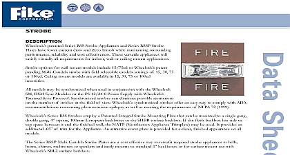
Fike P 1 15 01 Audible Strobe

File Preview
Click below to download for free
Click below to download for free
File Data
| Name | fike-p-1-15-01-audible-strobe-9054123687.pdf |
|---|---|
| Type | |
| Size | 747.61 KB |
| Downloads |
Text Preview
AUDIBLE STROBE Patented 2 WIRE Series AS Audible Strobe Appliance s offers features with Less Current and Zero Inrush The audible provides a choice of either a continuous horn tone or temporal pattern 3 tone when constant voltage from a Fire Alarm Control Panel is applied Each tone has 3 dBA settings to choose from All may be Synchronized when used in conjunction with the Series SM DSM Sync Module Additionally the audible may be silenced while strobe activation 20 105A 106A 107A 108A Series AS Audible Strobes are designed for maximum performance and cost effectiveness while meeting or exceeding the latest of NFPA 72 National Fire Alarm Code ANSI 117.1 National Standard for Accessible and Usable Buildings and UL Standard 1971 Standard for Signaling Devices for The Impaired and UL 464 Audible Signal Appliances Series AS Strobe Appliances when properly specified and installed in with NFPA ANSI standards can provide the Equivalent Facilitation allowed under ADA Accessibility ADAAG General Section 2.2 by meeting or exceeding the illumination which results from the ADA strobe intensity of 75 candela at 50 feet This is an illumination of 030 lumens per square foot When used the Wheelock Series SM or DSM Sync Module synchronization of the continuous horn tone provides the temporal 3 tone mandated by NFPA 72 1993 with an effective date of July simultaneously for all audible appliances Listed Approved Include Underwriters Laboratories UL 1971 and UL464 Listings FCC Part 15 Pending European CE New York City MEA California State Fire Marshal CSFM Chicago BFP compliant Meets OSHA 29 Part 1910.165 CURRENT INRUSH 2 Wire Appliance Continuous Horn or Temporal code 3 Tones Selectable dBA levels in both tones AS Audible Strobe Appliances available in Wall mount models Wall mount available in 15 15 75 75 and 110 candela intensity Tone Anechoic 90 95 99 dBA Reverberant 82 88 or 91 dBA Code 3 Tone Anechoic 90 95 99 dBA Reverberant 75 82 or 85 dBA 15 75 candela wall mounted strobes are listed at 15 candela under UL Standard 1971 and meet 75 intensity on axis for ADA guidelines with low current draw models can be Synchronized by adding the Series SM or DSM Sync Module to the NAC circuit the Audible Maintain the Temporal Pattern when 2 or more appliances are in an area Meets NFPA for Temporal Evacuation Notification the Strobe Maintain True 1 Flash per second when using 2 or more visual appliances within the field view Meets ADA and NFPA to Silence the Audible while maintaining the strobe flash FEATURES ON 2 WIRES S 10th Street P O Box 610 Blue Springs Missouri 64013 0610 U S A 816 229 3405 816 229 4615 www fike com No P 1.15.01 1 AND ORDERING INFORMATION Please read these specifications and associated installation instructions carefully before using specifying or this product Failure to comply with any of these instructions cautions and warnings could result in improper installation and or operation of these products in an emergency situation which could result in property and serious injury or death to you and or others Notes are designed to flash at 1 flash per second minimum from 20 31VDC Note that NFPA 72 1996 a flash rate of 1 to 2 flashes per second and ADA Guidelines specify a flash rate of 1 to 3 flashes per candela ratings represent minimum effective Strobe intensity based on UL 1971 AS Strobe products are UL 1971 for indoor use with a temperature range of 32 F to 120 F to 49 and maximum humidity of 85 Sync Modules are rated for 3.0 amperes at 24 VDC DSM Dual Sync Modules are rated for 3.0 amperes per circuit maximum number of interconnected DSM modules is twenty 20 15cd Strobe 15 75cd Strobe 75cd Strobe 110cd Strobe Module Sync Module P N P N CURRENT Amperes Audible Strobe the 3 Audible Settings 20 24 and 31 VDC Current with Hi dBA Setting 99 dBA Current with Med dBA Setting 95 dBA Current with Low dBA Setting 90 dBA VDC VDC VDC VDC VDC VDC VDC VDC VDC Average current per actual Wheelock Production Testing at 20 24 31 VDC DIAGRAMS FOR ALL MODELS Appliances Synchronized with Multiple DSM Modules Appliances Synchronized with DSM Module Single NAC Circuit without Audible Silence Feature Appliances Synchronized with SM Module Single Class NAC Circuit with Audible Silence Feature APPLIANCE NON SYNCHRONIZED AS and FACP must be set on continuous horn tone to achieve synchronized temporal code 3 tone and connected the SM or DSM Sync Module Wheelock products must be used within their published specifications and must be specified applied installed operated maintained and operationally tested in accordance with their instructions at the time of installation and at least twice a year or more often and in accordance with local and federal codes regulations and laws Specification application installation operation maintenance and testing be performed by qualified personnel for proper operation in accordance with all of the latest National Fire Association NFPA Underwriters Laboratories UL National Electrical Code NEC Occupational Safety Health Administration OSHA local state county province district federal and other applicable building and fire guidelines regulations laws and codes including but not limited to all appendices and amendments and the of the local authority having jurisdiction AHJ Contact Wheelock for Instructions P83509 Series AS and Information sheet on these products These documents do undergo periodic changes It is important that you have information on these products These materials contain important information that should be read prior specifying or installing these products including Use series as only on circuits with continuously applied operating voltage Do not use series as on coded or current required by all devices connected to system primary and secondary power sources ratings on signaling circuits to handle peak currents from all appliances on those circuits flash rate from multiple strobes within a person field of view voltage applied to these products must be within their rated input voltage range of 110 Candela strobe products in sleeping areas in office areas and other specification and installation issues circuits in which the applied voltage is cycled on and off as the strobe may not flash to comply with the installation instructions or general information sheets could result in improper application and or operation of these products in an emergency situation which could result property damage and serious injury or death to you and or others size AWG length and ampacity should be taken into consideration prior to design and of these products particularly in retrofit installations Fike Corporation All Rights Reserved No P 1.15.01 1 August 2005 Specifications are subject to change without notice


