Fike Photoelectric Smoke Detector D1174

File Preview
Click below to download for free
Click below to download for free
File Data
| Name | fike-photoelectric-smoke-detector-d1174-4236598107.pdf |
|---|---|
| Type | |
| Size | 833.96 KB |
| Downloads |
Text Preview
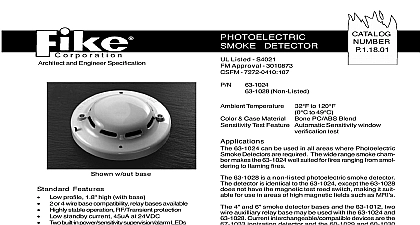
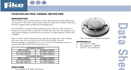
Architect and Engineering Specification w out base profile 1.8 high with base or 4 wire base compatibility relay bases available Features Highly stable operation RF Transient protection Non directional smoke chamber Removable smoke labyrinth for cleaning or replace standby current 45uA at 24VDC built in power sensitivity supervision alarm LEDs resistant security locking feature magnetic go no go detector test feature Sensitivity window verification function meets requirements in NFPA 72 Chapter 7 Inspection and Maintenance Compatible with 67 1033 ionization detectors compatible with Hochiki SLK and SIH bases Source Voltage Voltage Voltage Current Current Current Velocity Range Infrared Diode 30.0 VDC 33.0 VDC VDC 24 VDC max 24 VDC max 24 VDC fpm MODULE MODULE MODULE MODULE MODULE DETECTOR Listed S4021 Approval 3009768 7272 0410 107 Non Listed Temperature to 120 to 49 Case Material Bone PC ABS Blend Test Feature Automatic Sensitivity window test 63 1024 can be used in all areas where Photoelectric Detectors are required The wide range smoke cham makes the 63 1024 well suited for fires ranging from smol to flaming fires 63 1028 is a non listed photoelectric smoke detector detector is identical to the 63 1024 except the 63 1028 not have the magnetic test reed switch making it suit for use in areas of high magnetic fields such as MRI 4 and 6 smoke detector bases and the 63 1012 two auxilliary relay base may be used with the 63 1024 and Current interchangeable compatible devices are the ionization detector and the 60 1029 and 60 1030 detectors 63 1024 photoelectric smoke detector utilizes two bi LEDs for indication of status In a normal standby the LEDs flash Green every 3 seconds When the senses that its sensitivity has drifted outside the listed sensitivity window the LEDs will flash Red every 3 When the detector senses smoke and goes into the LEDs will latch ON Red 2001 Issue S 10th St P O Box 610 cid 127 Blue Springs MO 64013 0610 U S A cid 127 816 229 3405 cid 127 Fax 816 229 0314 cid 127 E mail fpssales fike com detector utilizes an infrared LED light source and sili photo diode receiving element in the smoke chamber a normal standby condition the receiving element re no light from the pulsing LED light source In the of a fire smoke enters the detector smoke chamber light is reflected from the smoke particles to the receiv element The light received is converted into an elec signal are processed and compared to a reference level when two consecutive signals exceeding the reference are received within a specified period of time the time circuit triggers the SCR switch to activate the alarm The LEDs light continuously during the alarm pe Sensitivity Test Feature 63 1024 Photoelectric Smoke Detector has a built in sensitivity test feature normal condition both LED flash green When the sensitivity drifts outside of its sensitivity both LED flash red the alarm state both LED are red continuously When the sensitivity drifts outside of its sensitivity and both LED flash red the device needs to be or returned to the factory for cleaning Refer to Technical Bulletin HA 97 for cleaning informa spacing smoke detectors following the guidelines in NFPA 72 base the number and location of on an engineering survey of the area to be detected Photoelectric smoke detectors cover 900 sq ft contractor shall furnish and install where indicated on plans Fike 63 1024 photoelectric smoke detectors The detector head and twist lock base shall be UL compatible with a UL listed fire alarm panel base shall permit direct interchange with Fike 63 1025 photoelectric heat detector 67 1033 ionization smoke detector and or 60 1029 60 1030 fixed tempera heat detectors The base shall be appropri twist lock base In the event of partial or complete retro the 63 1024 maybe used in conjunction with or as a for Fike detectors 63 1007 63 1016 and the on most HSB and HSC base applications smoke detector shall have two flashing status LEDs for supervision When the detector is in standby condi the LEDs will flash Green When the detector is outside UL listed sensitivity window the LEDs will flash Red the detector is actuated the flashing LEDs will latch The detector may be reset by actuating the control reset switch sensitivity of the detector shall be capable of being mea It shall be possible to perform a functional test of detector without the need of generating smoke The of the detector shall be monitored automatically continuously to verify that it is operating within the Listed range facilitate installation the detector shall be non polarized and RF transient suppression techniques shall be to minimize false alarm potential Auxiliary SPDT shall be installed where indicated vandal resistant security locking feature shall be used those areas as indicated on the drawing The locking fea shall be field removable when not required NO D1174 Copyright 2001 by Fike Corporation All rights reserved PRINTED IN U S A