DSC FSD 100 UM EN NA R001

File Preview
Click below to download for free
Click below to download for free
File Data
| Name | dsc-fsd-100-um-en-na-r001-7803249561.pdf |
|---|---|
| Type | |
| Size | 1.32 MB |
| Downloads |
Text Preview
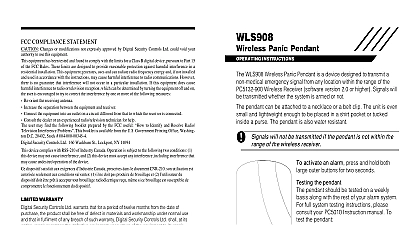
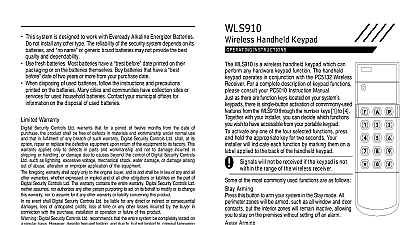
FSD 100 Detector Sensitivity Meter Guide This document contains information on limitations regarding use and function and information on the limitations as to liability the manufacturer Read the entire manually carefully OF CONTENTS 1 of the Box 2 Installation 2 Indicators 3 4 Up Power Down 4 Detector Testing 6 Test Records 7 Test Records 8 Tester Status 9 A B Troubles 11 Measurement Conversion 11 FSD 100 Smoke Detector Sensitivity Meter is intended for comprehensive in of the WS 4916 FSA210 and FSA410 Series Smoke Detectors The is hand held and battery operated providing 20 hours of continuous opera and stores up to 500 detector tests Volt alkaline battery provides 20 Hrs minimum operation battery check displays remaining battery capacity Reverse Polarity Protection shutdown 4 minutes after last key press features are accessed using 4 pushbuttons and retrieval of up to 500 detector tests stored in non volatile memory records to PC using MicroSoft HyperTerminal software Date Time Model and Version Date of Manufacture and Serial for all tests Troubles low sensitivity high sensitivity sensor fault sensor fault errors errors already transmitted Status Alarm Sensor Trouble fault Battery Smoke Detector Alarm sensor fault temperature warning of the Box FSD 100 tester includes the following 100 Smoke Detector Sensitivity Meter Procell PC1604 Alkaline 9VDC Battery Local Download KIT DB09 kit adaptor Guide Reference Guide Installation FSD 100 is shipped with a battery Remove the rear cover Remove the battery from the battery compartment Remove the plastic protection from the battery terminals battery as indicated in the battery compartment 1 Battery Replacement Procell Alkaline 9VDC Replace battery with Duracell Procell PC1604 Alkaline 9VDC Battery placement of the battery will NOT damage the unit and replacement of battery will NOT delete stored records will be prompted to set date and time on first power up following battery and Indicators FSD 100 displays all information on a 32 character LCD A PC LINK connec is located on the right side of the unit for downloading data to a PC use of the in Use of these keys is indicated on each screen The list below indi the general use of these keys keys varies depending on the screen you are and to Scroll forward through menu selections from the Ready Moves cursor to the right in time and date programming to Scroll back through menu selections from the Ready Moves cursor to the left in time and date programming to next option within a menu sequence Testing and Downloading value selected with programming and keys in time and off device during power down a menu selection Up Power Down Up power up the model name and version of the tester is displayed on top line remaining battery capacity is displayed on the second line 99 indicates that the battery is fully charged battery when 1 is indicated screen will be displayed for 2 seconds Capacity the current number of tests stored in the tester out of a maxi of 500 tests screen will be displayed for 2 seconds Date Trouble screen will only be displayed if time and date are unprogrammed at first power up or after battery replacement to save date and time programming and advance to the next Screen screen is displayed 2 seconds after the Record Capacity screen is or after exiting Date and Time programming screen allows you to scroll through the 6 menu options available on tester V1.00 LIFE 99 CAPACITY FILLED DATE TRBL TO PROG Down tester can be powered down in two ways unit will automatically power down 4 minutes after the last regardless of the screen it is currently in the scroll key display the Press 5 times from the Ready mode screen for Power Down screen Press the to return to the Ready key twice to power down or press 2 Power Up and Main Flow Menu 2 seconds to Power up V1.00 LIFE 99 DATE TRBL TO PROG INC EXIT YYYY MM DD or to move cursor indicated is for the key to increment value to exit CAPACITY FILLED Second Second Date FOR MENUS FOR READING FOR RECORDS FOR DOWNLOAD FOR INFO FOR PROG FOR DOWN the key will scroll through the menu in the sequence To scroll in the reverse direction use the key Detector Testing the steps indicated in figure 3 until the TRIGGER WAIT FOR BEEP screen appears the LED Test Button located on the smoke detector with tester the tester less than 2.5 cm 1 Inch from the center of the smoke detector Smoke Detector and the FSD 100 Tester will indicate that data is being trans and received by sounding a series beeps from each device data transmission is completed the beeping will stop and the FSD 100 will display the TEST COMPLETE DATA SAVED screen followed by a second delay After the delay the PRESS FOR DATA REVIEW screen will appear Pressing will begin the test review See Paragragh 2.3 View Pressing the or keys will return you to the TESTER Test Records screen 3 Testing FOR MENUS FOR MENUS FOR FOR READING READING next item READY READY READ EXIT READ EXIT DEVICE DEVICE FOR BEEP FOR BEEP COMPLETE COMPLETE SAVED SAVED Second Button Button 1 Minute NO SIGNAL NO SIGNAL TO EXIT TO EXIT Tester less than Tester less than Detector in the position indicated Detector in the position indicated 1 inch from 1 inch from FOR FOR REVIEW REVIEW Paragraph 2.3 Data Records Test Records Test Records section can be entered directly after a Smoke Detector Test the PRESS review the preceding test only FOR DATA REVIEW screen appears This option allows you records can be reviewed by following the steps indicated in figure 4 4 Viewing Test Records FOR MENUS FOR RECORDS next menu item FOR XXX 500 FOR XXX 500 EMPTY TO EXIT 2.5 FT 25 77 ULC 1.00 4XXXX LIFE 99 TIME DATE HH MM FOR MENU 12345678 12345678 Smoke Low Sensitivity Smoke High Sensitivity Smoke Sensor Test Failed Smoke Sensor Fault Heat Sensor Fault