DSC GS-8ANTP - Antenna Placement and Installation Instructions - EN

File Preview
Click below to download for free
Click below to download for free
File Data
| Name | dsc-gs-8antp-antenna-placement-and-installation-instructions-en-1350684297.pdf |
|---|---|
| Type | |
| Size | 1.92 MB |
| Downloads |
Text Preview
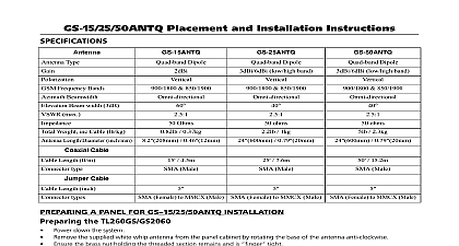
GS 8ANTP Placement and Installation Instructions GS 8ANTP is an indoor remote antenna for the SCW9055 SCW9057 It increases the signal strength received by the communicator Input Power Beam Width 3dB Weight Temperature Temperature Cable Length Type MHz with 8 LMR 100 cable max Ohms 0.275lbs x 80mm x 20mm 5.5 x 3.15 x 0.8 20 to 70 4 to 158 40 to 80 40 to 176 8 R A Male There are hazardous voltages up to 240VAC 40VA and or TNV circuits within the panel cabinet of the Box 1 Antenna 1 Installation instructions 2 Self tapping screws 2 Wall plugs Communicators 3G2055 3G2075 the Existing Antenna Cable from the Alarm Panel 2 Plugs 1 Slot baffle 2 Double sided adhesive 1 Cable tie TL2553G GS2055 Disconnect the AC and telephone lines from the SCW9055 9057 Remove the front cover of the alarm panel Disconnect the battery wire and ribbon cable from the connectors on the front panel Carefully disconnect the antenna cable from the radio module and the on board antenna on the communicator To remove the cable grasp the end cable connector and lift straight up as shown in Figure 1 1 Removing the Cable the retaining tab at the bottom of the communicator and lift the bottom of the PCB the PCB down to remove from the top retaining clips and remove the antenna cable from the enclosure Use these instructions in conjunction with the TL2X53G 3G20X5 GS20X5 Installation Manuals Disconnect and telephone lines during the installation of the GS 8ANTP antenna Use the GS 8ANTP antenna in conjunction the supplied coaxial cable only The GS 8ANTP antenna must be installed by service persons only Use caution installing the GS 8ANTP antenna near power lines the PCB back in place by sliding it up under the top retaining clips Gently press down on the PCB until the bottom tab snaps into place the New Antenna Cable the MMCX connector end of the provided extension antenna from the back of the alarm panel through the opening above the terminal block Carefully connect the MMCX connector to the radio module The antenna connector must be placed across the PCB as indicated in Figures 2 and 3 below 2 TL25XGS GS20X5 3 TL2XX3G 3G20XX the extension cable to the plastic base of the alarm panel using the supplied cable tie as shown in Figure 4 4 Securing the Antenna Connector the battery wire and ribbon cable into the connectors on the front of the alarm panel Re attach the front cover by snapping it into place Antenna Placement Test choose a suitable location for the GS 8ANTP perform an antenna placement test by moving the antenna around to determine the which displays the highest signal strength The relative signal strength is indicated in programming section 850 Cellular Strength of the control panel See the communicator installation manual for more details regarding antenna placement The antenna must be installed on the wall using the supplied hardware Ensure the antenna is mounted as high as possible i e to the ceiling to obtain maximum signal strength Avoid installing the antenna on or near metallic surfaces The antenna must only be used indoors in non hazardous locations only Locate the antenna away from possible sources of electrical interference The antenna must be mounted in a vertical orientation to obtain optimal signal strength Refer to Figure 5 below the signal strength is poor try relocating the antenna left or right up or down a few inches Antenna Installation installing the GS 8ANTP to the proposed location 5 Antenna Orientation the antenna is mounted vertically see Figure 5 the antenna to the wall using the screws and wall plugs or the double sided adhesive tape provided The adhesive tape must not be used for mounting in UL ULC installations Use the full length of the antenna cable supplied do not cut or splice the cable Cable can be surface mounted or fished through the wall on which the antenna is mounted If surface mounted the knock on the slot baffle must be removed prior to running antenna wire see Figure 6 6 Slot Baffle Knock out turning the cable through a 90 degree corner ensure that the bend radius is more than 1 the antenna is in a physically secure location to avoid tampering Any excess cable should be coiled close to the communicator unit Do not over coil the cable ensure the coil diameter is not than 6 When using the full length of the cable for the antenna installation ensure the cable does not place strain on the equipment Ensure wiring is routed in a manner that is not hazardous to the end user loosening of terminal connections and or strain on wires Antenna Placement Confirmation the GS 8ANTP antenna is mounted retest it in the proposed location to verify the signal strength is acceptable WARRANTY Security Controls DSC warrants that for a period of 12 from the date of purchase the product shall be free of in materials and workmanship under normal use and that in of any breach of such warranty DSC shall at its option or replace the defective equipment upon return of the equip to its repair depot This warranty applies only to defects in and workmanship and not to damage incurred in shipping or or damage due to causes beyond the control of DSC such lightning excessive voltage mechanical shock water damage or arising out of abuse alteration or improper application of equipment The foregoing warranty shall apply only to the orig buyer and is and shall be in lieu of any and all other warranties expressed or implied and of all other obligations or liabili on the part of DSC DSC neither assumes responsibility for nor any other person purporting to act on its behalf to modify to change this warranty nor to assume for it any other warranty liability concerning this product In no event shall DSC be liable any direct indirect or consequential damages loss of anticipated loss of time or any other losses incurred by the buyer in con with the purchase installation or operation or failure of this DSC recommends that the entire system be completely on a regular basis However despite frequent testing and due but not limited to criminal tampering or electrical disruption it possible for this product to fail to perform as expected Important Changes or modifications not expressly approved by could void the user authority to operate this equipment 2014 Tyco International Ltd and its Respective Companies All Rights Reserved Canada www dsc com Support 1 800 387 3630 Canada USA 905 760 3000 in China