DSC HS2016-HS2032-HS2064-HS2128 V1 35 - User Guide - English

File Preview
Click below to download for free
Click below to download for free
File Data
| Name | dsc-hs2016-hs2032-hs2064-hs2128-v1-35-user-guide-english-5087192364.pdf |
|---|---|
| Type | |
| Size | 2.51 MB |
| Downloads |
Text Preview
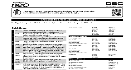
To download the full user manual and register your product please visit or scan the QR code to the right E E Alarm Panel Guide of Contents Icon and LED Keypad Symbols Keypad Models General System Operation Testing Your System Monitoring Maintenance Alarm System Setting Methods Setting the System Infinite Exit Delay Away Setting the System with the Keypad Exit Delay Time Restart Alarm Cancel Window Using 2 way Wireless Keys and Proximity Tags Arming the System with a 2 Way Wireless Key To Arm the System with a 2 way wireless key Arming the System with a Proximity Tag Alarm System Unsetting Methods Disarming Unsetting the System Engineer Reset Downloading Enable Opening the Access Code Menu Adding Changing and Deleting Access Codes Burglary Verification Swinger Shutdown Call Waiting Fire Alarm Verification Silence Fire or CO Alarm System Lockout due to Invalid Attempts User Labels LCD keypads only Regular Maintenance and Troubleshooting Cleaning and Maintenance System Information Service Contact Information Smoke Detectors Fire Escape Planning Carbon Monoxide Detectors 2 1.0 Quick Reference Quick Reference PowerSeries Neo Alarm System uses shortcut keys to access features on all models of When using an LCD keypad the PowerSeries Neo Alarm System uses a menu based nav system The scroll keys can be used to navigate through the list of options contained within current menu For more information see 2.0 your Keypad Look up detailed on any of the listed actions using the accompanying Section number detailed information about the PowerSeries Neo Alarm System refer to the full online manual can be accessed from the DSC com website features must be enabled by installer Groups are not permitted in UL listed installations Lights Set Set Exit Indicates system normal Must be on to set system All zones must be or bypassed and the system unset for this light to activate Indicates system is set If the Ready light and the Set light are both on an Exit is in progress On indicates a system malfunction or tamper Flashing indicates that the has a low battery condition Follow the instructions displayed or enter 2 to trouble Correcting the trouble turns off the indicator Power Indicates AC Power is present The AC Power light will turn off when is absent for 2 seconds Access Code for 2 seconds Access Code and Unsetting Set Set Set Setting Set Quick Exit Setting Sequence All bypass commands begin with 1 Access Code Individual Zones All Open Zones Last Bypass set in stay mode 1 Access Code Access Code Code Digit Zone OR Scroll Bypass Options Scroll Clear Bypasses digit zone s 9 9 5 OR 3 digit zone s Scroll Bypass Options Prg Bypass Group OR Scroll Bypass Options Scroll Bypass Group Bypass Bypass Group Bypass Group Functions Time and Date Chime ON OFF Brightness Contrast Master Code 0 1 Access Code OR Master Code 1 2 Master Code 1 3 3 1.0 Quick Reference User Smoke Detectors Troubles Alarms System Test Volume Master Code Access Code 1 OR 7 2 Access Code Access Code Master Code 0 4 Master Code 1 4 4 2.0 Understanding Your Keypad Understanding Your Keypad PowerSeries Neo Alarm System supports a variety of wireless hardwired and proximity LCD LED and Icon keypads All keypads come equipped with the LED status lights in section 1 Quick Reference HS2LCD series keypads display system messages on LCD screen HS2ICN series keypads display messages as described in the following section series keypads display messages via a series of numbered LEDs as described in the fol section All keypad versions will have a solid blue LED bar that is always on except when enrolled a proximity tag is presented and successfully read by the keypad Icon and LED Keypad Symbols Clock Digits 1 2 Colon Digits 3 4 to 8 Memory Stay Chime clock digits indicate the hour when the local clock is active 2 is also used to identify the zone number icon is the hours minutes divider and will flash once per when the local clock is active are the minute digits when the local clock is active The 3 and 4 are used to indicate the zone number for open zones alarm in memory These two digits combined with the clock 2 scroll one zone per second from the lowest number to the when scrolling through zones numbers identify troubles when 2 is pressed that there are alarms in memory that there are zones bypassed that the system is in Installer or User programming or the keypad is busy and the LED will flash If an Access is required while accessing menus this LED is ON and to indicate that the code is required that the panel is set in the Away Mode that there are fire and or CO alarms in memory that the panel is set in the Stay Mode icon turns on when the Chime function key is pressed to Door Chime on the system It will turn off when the chime key is pressed again to disable Door Chime 5 2.0 Understanding Your Keypad OPEN AC System Trouble Night Ready Light green icon is used with clock digits 1 and 2 to indicate activated not alarm on the system When zones are opened the icon will turn on clock digits 1 and 2 will scroll through violated zones that AC is present at the main panel that a system trouble is active that the panel is set in the Night Mode the Ready light is on the system is ready for setting If the of the Ready LED flashes for Force Setting enabled the flashes with force setable zones open on the partition the Set light is on the system has been set successfully Set Light red Keypad Models the following list if x 8 the system operates in 868MHz band Wireless Alphanumeric LCD keypad with Prox Tag support Wireless Alphanumeric LCD keypad with Prox Tag support Voice Promp LCD keypad LCD keypad with Prox Tag support keypad keypad with Prox Tag support keypad LCD keypad with wireless receiver LCD keypad with wireless receiver and Prox tag support keypad with wireless receiver keypad with wireless receiver and Prox tag support Alphanumeric LCD keypad keypad For additional information refer to the HS2TCHP User Manual systems compliant with EN50131 1 and EN50131 3 the HS2LED keypad shall be used in with an LCD type keypad HS2LCD P or HS2LCDRF P 8 or HS2LCDWF P 8 in to be