DSC PF-RFK55XX v1 0 EN FR SP POR 29007203R002

File Preview
Click below to download for free
Click below to download for free
File Data
| Name | dsc-pf-rfk55xx-v1-0-en-fr-sp-por-29007203r002-6048317529.pdf |
|---|---|
| Type | |
| Size | 4.88 MB |
| Downloads |
Text Preview
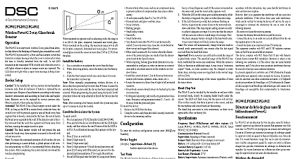
Installation Instructions Instructions d Instrucciones de instalaci Instru de instala Fran Espa Portugu Please refer to the System Installation Manual for information on limitations regarding product use and function and information on the limitations as to liability of the manufacturer These instructions shall be used in conjunction with the system Installation Manual of the Control Panel with which this equipment is intended to be used Ce manuel contient des informations sur les restrictions concernant le fonctionnement et l du produit et des informations sur les restrictions en ce qui concerne la responsabilit du fabricant La totalit du manuel doit lu attentivement Ce manuel doit utilis en conjonction avec le Manuel d du Panneau de contr Consulte el Manual de instalaci del sistema para obener informaci sobre las limitaciones del uso y funciones del producto as como las limitaciones de la responsabilidad del fabricante Estas instrucciones deber utilizarse conjuntamente con el Manual de instalaci del sistema del Panel de control con el que se vaya a utilizar este equipo Consulte o Manual de instala do sistema para obter informa acerca das limita relativas utiliza do produto e fun e informa acerca das limita relativas imputa de responsabilidades ao fabricante Estas instru devem ser utilizadas em conjunto com o Manual de instala do sistema do painel de controlo com o qual este equipamento se destina a ser utilizado 9 0 0 7 2 0 3 R0 0 2 Rotate 90 engage Instructions cid 129 PC1565 PK55XX keypads can be used on security systems with to 64 zones These keypads are compatible with the following DSC systems RFK55XX keypads combine a wireless receiver with the respective keypad Temperature range 10 to 55 14 to 131 Tempera range for UL ULC 0 to 49 32 to 120 Humidity MAX 93 R H Plastic enclosure protection degree IP30 IK04 Voltage rating 12VDC nominal Connects to control panel via 4 wire Keybus 1 keypad zone input PGM output PK55XX Current draw 50mA standby 125mA maximum RFK55XX Current draw 75mA standby 135mA maximum Wall mount tamper 5 programmable function keys Ready Green LED Armed Red LED Trouble Yellow LED AC LED Low temperature sensor Frequency 433.92MHz RFK55XX 433 Only Up to 32 wireless zones RFK55XX Only Zone not to be programmed as Fire type or 24h type Power keypad package includes the following parts Power keypad mounting screws end of line resistors should mount the keypad where it is accessible to designated of entry and exit Once you have selected a dry and secure loca perform the following steps to mount the keypad Keypad Removing the keypad from the backplate for the first time inner door labels tamper switch Instructions Position the keypad as indicated insert screwdriver and rotate Insert the screwdriver into slot at an angle and push Removing the keypad from backplate once mounted Open door holding it 90 to the keypad as shown below Insert screwdriver into slot located under the door hinge and the screwdriver Repeat steps 1 and 2 for left side Insert the screwdriver into slot at an angle and push and Wire Keypad Out Rotate 90 Slot Out Repeat steps 1 and 2 for right side Out to snap Secure Keypad to wall using mounting holes Use all 4 screws provided mounting on a single gang box Place keypad into hooks on the backplate and swing down to engage Run wire through wiring slot or knockouts Connect Keybus and PGM Zone to keypad Place tamper switch into tamper hole on backplate Remove keypad from hooks Place keypad into backplate ensure the wire pushed back into the wall as much as possible Route the wire inside keypad ensuring high components are avoided Snap the front assem closed ensuring that there is no pressure to the keypad from the wire If any tension found between the front keypad assembly and wiring open the keypad reroute the wire and close again Repeat these until the keypad is closed properly Before wiring the unit ensure that all power AC transformer and battery disconnected from the control panel Connect the four Keybus wires from the con panel red black yellow and green to keypad terminals Refer to diagram zone or output If programmed as an input you can con a device such as a door contact to terminal of the keypad This elim the need to run wires back to the panel for the device To connect the run one wire from the device to the terminal and the other wire the device to the B black terminal For powered devices run the red to the R positive terminal and the black wire to the B negative When using end of line supervision connect the zone according one of the configurations outlined in your system Installation Manual If the terminal is programmed as an output the output follows the programmed in Section 080 A small relay buzzer or other DC device may be connected between the positive supply voltage the terminal maximum load is 50mA Option 4 For UL Residential Fire Installations use at least one addi DSC compatible keypad in conjunction with an RFK55XX keypad or install the RFK55XX 433 keypads within 3 feet the control unit and mechanically protect the keybus wires Power all wiring is complete and the equipment is secured to the build structure with at least two screws apply power to the control panel Connect the battery leads to the battery Connect the AC transformer more information on control panel power specifications see the panel Installation Manual the Keypad are several program options available for the These are described Programming the key is similar to programming rest of the system When are in the keypad pro sections the key will display which options turned on along the top of display To turn an option or off press the number corresponding to the option on the number The numbers of the options that are currently turned ON will be For example if options 1 and 4 are on the display will like this on the different keypad displays information on programming the rest of your security system refer to your system Installation Manual LCD Labels LCD programming is done per keypad If more than one LCD key is present on the system labels programmed at one keypad can broadcast to all other LCD keypads Perform the following procedure order to broadcast labels 1 Program one LCD keypad completely 2 Make sure all LCD keypads are connected to the Keybus 3 Enter keypad programming by pressing cid 2 8 Installer then enter section 998 at the keypad that was pro The keypad will now broadcast all the information pro to all the other LCD keypads on the system 4 When the keypad is finished press the key to exit Label broadcast from this keypad is only compatible with other and RFK5500 Keypads Programming Only keys for 2 seconds to enter language programming to the desired language and Press cid 2 to select If section 077 option 4 is OFF language programming only be performed while in installers programming the Keypad keypad will need to be assigned to a partition and slot if supervi