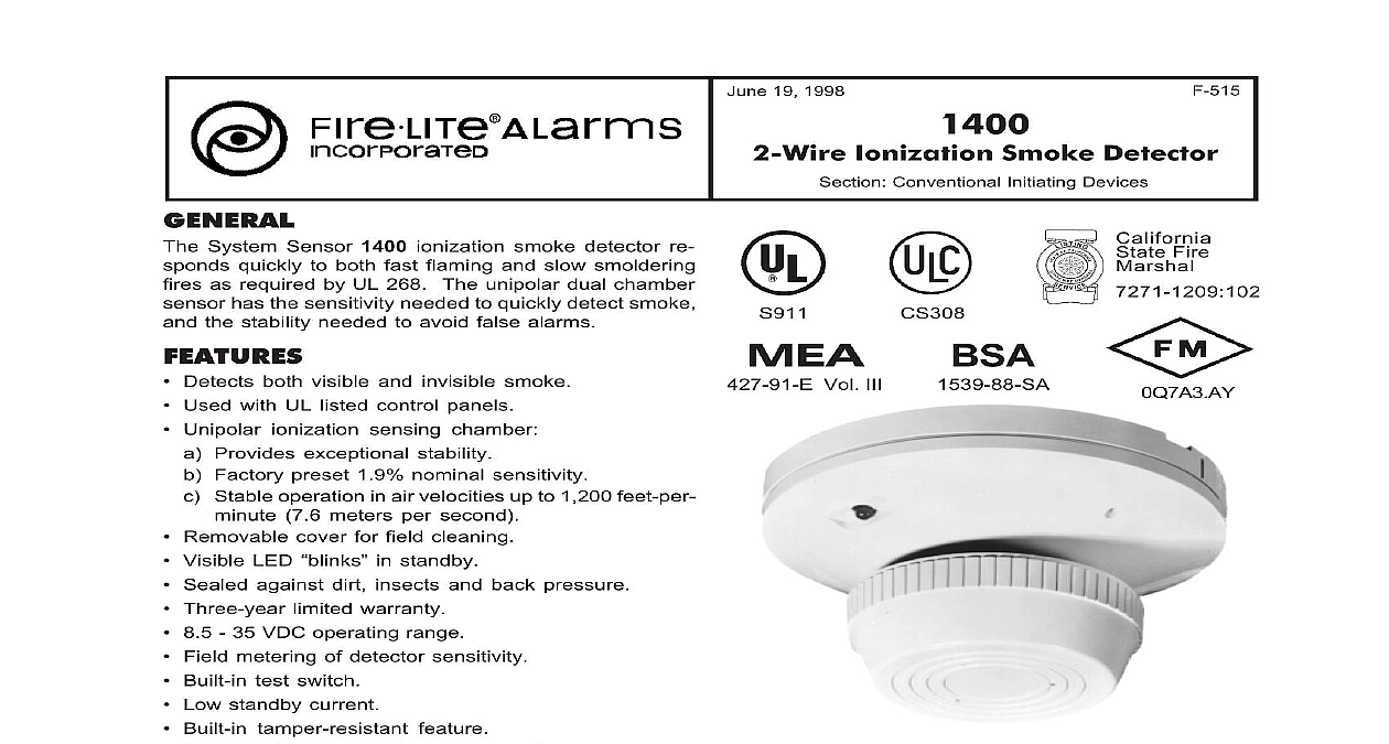
Fire-Lite 1400 2-Wire Smoke
File Preview
Click below to download for free
Click below to download for free
File Data
| Name | fire-lite-1400-2-wire-smoke-8402391576.pdf |
|---|---|
| Type | |
| Size | 735.49 KB |
| Downloads |
Text Preview
GENERAL System Sensor 1400 ionization smoke detector re quickly to both fast flaming and slow smoldering as required by UL 268 The unipolar dual chamber has the sensitivity needed to quickly detect smoke the stability needed to avoid false alarms Detects both visible and invisible smoke Used with UL listed control panels Unipolar ionization sensing chamber Provides exceptional stability Factory preset 1.9 nominal sensitivity Stable operation in air velocities up to 1,200 feet per 7.6 meters per second Removable cover for field cleaning Visible LED cid 147 blinks cid 148 in standby Sealed against dirt insects and back pressure Three year limited warranty 8.5 35 VDC operating range Field metering of detector sensitivity Built in test switch Low standby current Built in tamper resistant feature Direct surface or electrical box mounting Remote LED option Insect resistant screening maximum to 0.020 0.508 openings SEMS screws for easy wiring to contribute to life safety fire protection and property Superior to photoelectric detectors in de fast flaming fires Superior to bipolar detectors in false alarms AND OPERATION 1400 Series ionization smoke detectors contain a dual source dual unipolar chamber detection de which will sense the presence of smoke particles by fast combustion as well as slow smoldering Additional key features include a blinking LED status indicator an easily visible alarm indica and provision for convenient field test and metering back of the detector is sealed to block back pressure flow The chamber is protected by a fine mesh 0.020 mm screen to minimize problems with dust dirt 19 1998 Ionization Smoke Detector Conventional Initiating Devices Vol III Fire insects If cleaning is required the cover is easily with a special tool providing access to the and chamber to perform a thorough cleaning 1400 detectors are intended for use with Fire cid 149 Lite listed control panels Maximum number of detectors zone depends on capacity of panel see Fire cid 149 Lite De Compatibility Document 15384 Easy to install and this detector is designed for direct surface mounting bracket included or mounting to a octagonal or smaller box Easy to wire screw termi allow fast and simple field wiring of in out and re annunciator connections The wiring diagram page shows the correct method for wiring Model 1400 detec prevent wiring mistakes observe polarities and make that each conductor is identified A copy of the and maintenance instructions is packaged with detector For further information refer to NFPA 72 on Automatic Fire Detectors cid 148 and to local Au Having Jurisdiction For Canadian applications always use a mounting elec box document is not intended to be used for installation purposes We try to keep our information up to date and accurate We cannot cover all specific applications or all requirements All specifications are subject to change without notice For information contact Fire cid 149 Lite Phone 203 484 7161 FAX 203 484 7118 Clintonville Road Northford Connecticut 06472 and Manufacturing System Certified to Standard ISO 9001 in the U S A cid 151 Page 1 of 2 SPECIFICATIONS detector shall be an ionization type Model 1400 manufactured by System Sensor Wiring connections be made by means of SEMS screws Detector will a visible LED which will blink in standby and latch on alarm The detector shall have a sensitivity of 1.9 as measured in the UL smoke box The detector and cover should be easily removable for clean It shall be possible to perform a sensitivity and func test on the detector without the need of generating The detector shall have a mounting bracket that for mounting to a 3 1 2 8.89 cm or 4 10.16 cm box or a 4 10.16 square electrical box Model 1400 Ionization LED local alarm Yes LED annunciator capability Yes voltage range 8.5 35 VDC limits Standby max 100 cid 181 A 24 V Alarm current typical See Note 1 Alarm current max See Note 1 ripple voltage 4 V peak to peak voltage 2.5 VDC time 0.3 seconds time 2 seconds 3.12 7.9 cm high 5.5 13.9 cm diameter velocity rating 1,200 feet per minute 7.6 meters per maximum 0.7 lbs 317.5 grams 4 10.16 cm square box 1.5 3.81 cm min with plaster ring 3.5 8.89 cm or 4 10.16 cm box 50 60 or 75 mm boxes temperature 32 cid 176 F to 120 cid 176 F 0 cid 176 C to 49 cid 176 C humidity 10 to 93 relative humidity non alarm Reset by momentary power interruption features Test port Insert 0.1 2.54 mm maxi diameter allen wrench or screwdriver into test port detector housing Test module Using a standard interface insert MOD400R plug into detector port Fulfills calibrated sensitivity test per NFPA 1 Two wire control panels must limit current to 100 mA less INFORMATION Smoke Detector 2 wire Surface Annunciator LED Field test module for all of the System Sen 400 Series smoke detectors WIRING DIAGRAM 2 of 2 cid 151 DF 50484


