Fire-Lite FC XRM70 Voice Evac Transformer
File Preview
Click below to download for free
Click below to download for free
File Data
| Name | fire-lite-fc-xrm70-voice-evac-transformer-1423687950.pdf |
|---|---|
| Type | |
| Size | 697.65 KB |
| Downloads |
Text Preview
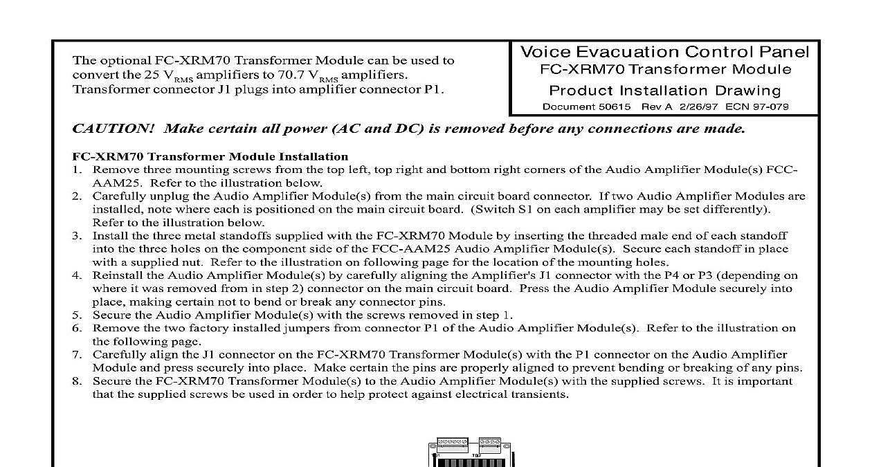
The optional FC XRM70 Transformer Module can be used to the 25 V connector J1 plugs into amplifier connector P1 amplifiers to 70.7 V amplifiers Evacuation Control Panel Transformer Module Installation Drawing 50615 Rev A 2 26 97 ECN 97 079 Make certain all power AC and DC is removed before any connections are made Transformer Module Installation Remove three mounting screws from the top left top right and bottom right corners of the Audio Amplifier Module s FCC Refer to the illustration below Carefully unplug the Audio Amplifier Module s from the main circuit board connector If two Audio Amplifier Modules are note where each is positioned on the main circuit board Switch S1 on each amplifier may be set differently to the illustration below Install the three metal standoffs supplied with the FC XRM70 Module by inserting the threaded male end of each standoff the three holes on the component side of the FCC AAM25 Audio Amplifier Module s Secure each standoff in place a supplied nut Refer to the illustration on following page for the location of the mounting holes Reinstall the Audio Amplifier Module s by carefully aligning the Amplifier J1 connector with the P4 or P3 depending on it was removed from in step 2 connector on the main circuit board Press the Audio Amplifier Module securely into making certain not to bend or break any connector pins Secure the Audio Amplifier Module s with the screws removed in step 1 Remove the two factory installed jumpers from connector P1 of the Audio Amplifier Module s Refer to the illustration on following page Carefully align the J1 connector on the FC XRM70 Transformer Module s with the P1 connector on the Audio Amplifier and press securely into place Make certain the pins are properly aligned to prevent bending or breaking of any pins Secure the FC XRM70 Transformer Module s to the Audio Amplifier Module s with the supplied screws It is important the supplied screws be used in order to help protect against electrical transients S1 Backup Select Step 2 mounting screws Step 1 Supply Audio Module connector P3 of main circuit board 4 5 Audio Module on P4 of the circuit board 4 5 mounting screws Step 1 Evacuation Control Panel Circuit Board Standoff 3 Standoff 3 of board Audio Modules with nut 3 Standoff 3 Standoff 3 Audio Modules Standoff 3 Audio Modules Factory Installed Jumpers on P1 Each Amplifier Module Must be to Install the FC XRM70 Module Step 6 Module 7 8 of 2 50615 Rev A ECN 97 079 2 26 97


