Fire-Lite System Sensor SpectAlert Ceiling Mount Series (SC Strobes and PC Horn Strobes)

File Preview
Click below to download for free
Click below to download for free
File Data
| Name | fire-lite-system-sensor-spectalert-ceiling-mount-series-sc-strobes-and-pc-horn-strobes-8167459203.pdf |
|---|---|
| Type | |
| Size | 829.06 KB |
| Downloads |
Text Preview
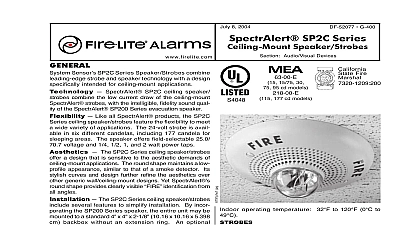
July 8 2004 cid 127 G 450 Mount Series Strobes and PC Horn Strobes Audio Visual Devices 61 00 E Fire Strobe top and PC Horn Strobe bottom voltage 24 VDC and FWR unfiltered terminals 12 to 18 AWG 3.25 to 0.75 mm voltage range 24 volts 16 33 volts NOTE cd models tested at 20 33 V FWR and 16 33 VDC voltage range with Sync cid 127 Circuit module 24 17 33 volts NOTE 177 cd models tested at 21 33 V and 17 33 VDC Patent Numbers 6,049,446 6,057,778 D424,465 is a registered trademark and Sync cid 127 Circuit is a of System Sensor Sensor SpectrAlert Ceiling Mount Series and Horn Strobes offer a fresh approach to the needs of ceiling mount applications Like the original SpectrAlert line the Ceiling Mount Series offers significant current reductions over other ceiling mount strobes and horn SpectrAlert Ceiling Mount strobes and horn are available in seven different candelas including candela for sleeping areas The horn strobe tones are with a three position switch on the back of unit Selections include electromechanical and 3 KHz Temporal 3 and Non Temporal 3 patterns and high low volume SpectrAlert Ceiling Mount strobes and horn offer a design that is sensitive to the aesthetic de of ceiling mount applications The round shape main a low profile appearance similar to that of a smoke de Its stylish curves and design further refine the aes over other generic wall ceiling mount designs Yet round shape provides clearly visible from all angles SpectrAlert compact design also offers savings The strobe and horn strobe models to a 4 x 4 x 1 1 2 101.6 x 101.6 x 38.1 mm backbox take up little room in the backbox making connections With SpectrAlert round shape aligning the with the room walls is not necessary always lines up Lower current draw Available in 15 15 75 30 75 95 115 and 177 candela Horn strobe models include a three position switch for field horn tones electromechanical 3KHz temporal 3 high low dBA output Synchronizable with MDL Sync cid 127 Circuit module Ceiling specific shape profile and aesthetics Mounts to a 4 x 4 x 1 1 2 101.6 x 101.6 x 38.1 mm Round shape offers greater placement flexibility 6.8 172.72 mm diameter 4 x 4 x 1 1 2 101.6 x 101.6 x 38.1 mm operating temperature 32 to 120 0 to 49 humidity 95 as tested per UL 464 5.3 oz 150 grams Alarms is a Honeywell company document is not intended to be used for installation purposes We try to keep our product informa up to date and accurate We cannot cover all specific applications or anticipate all requirements specifications are subject to change without notice more information contact Fire cid 127 Lite Alarms One Fire Lite Place Northford Connecticut 06472 Phone 627 3473 Toll Free FAX 877 699 4105 07 08 04 Page 1 of 4 Max Max RMS Max Max RMS RMS CURRENT DRAW No Mount Candela RMS Current mA Current mA Current mA Notes All SC and PC strobes were only tested at the 16 33 Volt FWR DC Limits This does not include the 80 low end and the 110 high voltage limits 2 Horn Strobe current draws assume horn is set at Temporal 3 electromechanical tone and high audihbility Horn Tones Volume Volume Volume Volume Hz Interrupted Hz Interrupted Hz Interrupted Hz Interrupted 2 of 4 DF 52086 cid 127 07 08 04 or accessory Skirt or Mounting Surface Mount Backbox Skirt cid 127 07 08 04 Page 3 of 4 SPECIFICATIONS shall be a System Sensor SpectrAlert Model Listed to UL 1971 and be approved for fire protec service where ceiling mount strobes are permitted The shall be wired as a primary signaling notification and shall flash at 1 Hz over the strobe entire range The strobe light shall consist of a xenon tube and associated lens reflector system shall be a System Sensor SpectrAlert Model Listed to UL 1971 and UL 464 and be approved for protective service where ceiling mount horn strobes are The horn strobe shall be wired as a primary sig notification appliance and shall flash at 1 Hz over its operating range The strobe light shall consist of a flash tube and associated lens reflector system The shall have two tone options two audibility options and option to switch between a temporal 3 pattern and a non continuous pattern These options shall be se by a multi position switch Strobes shall be powered of the sounder with the removal of factory jumper wires The horn on horn strobe models operate on a coded or non coded power supply The strobes must be powered continuously for the to operate Information Number strobe 24 volt 15 candela red strobe 24 volt 15 candela white strobe 24 volt 1575 candela red strobe 24 volt 1575 candela white strobe 24 volt 30 candela red strobe 24 volt 30 candela white strobe 24 volt 75 candela red strobe 24 volt 75 candela white strobe 24 volt 95 candela red strobe 24 volt 95 candela white strobe 24 volt 115 candela red strobe 24 volt 115 candela white strobe 24 volt 177 candela red strobe 24 volt 177 candela white horn strobe 24 volt 15 candela red horn strobe 24 volt 15 candela white horn strobe 24 volt 1575 candela red horn strobe 24 volt 1575 candela white horn strobe 24 volt 30 candela red horn strobe 24 volt 30 candela white horn strobe 24 volt 75 candela red horn strobe 24 volt 75 candela white horn strobe 24 volt 95 candela red horn strobe 24 volt 95 candela white horn strobe 24 volt 115 candela red horn strobe 24 volt 115 candela white horn strobe 24 volt 177 candela red horn strobe 24 volt 177 c