Gamewell-FCI 2400 Photoelectric Detector

File Preview
Click below to download for free
Click below to download for free
File Data
| Name | gamewell-fci-2400-photoelectric-detector-5190426837.pdf |
|---|---|
| Type | |
| Size | 622.20 KB |
| Downloads |
Text Preview
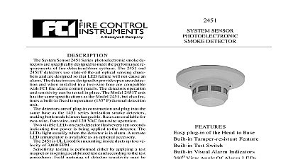
DESCRIPTION System Sensor 2400 Series photoelectronic smoke de are specifically designed to meet the performance re of fire detection alarm systems These detectors state of the art optical sensing chambers The detectors designed to provide open area detection and are compati with FCI fire alarm control panels The detectors opera and sensitivity can be tested in place The Model 2400T has the same specifications as the Model 2400 but in ad it features a built in fixed temperature 135o F thermal unit detector has an LED which flashes every ten seconds that power is being applied to the detector The lights steadily when the detector is in alarm A remote annunciator is available as an optional accessory 2400 and 2400T detectors include a tamper resistant that when used prevents removal of the detector the use of a tool testing is performed either by inserting a tool the recessed test switch opening or inserting a calibrated card according to the test procedures metering of detector sensitivity may be performed the aid of a voltmeter and test kit MOD 400R SENSOR DETECTOR Built in Tamper resistant Feature Built in Test Switch Built in Visual Alarm Indicator Remote LED Option Compatible with FCI Control Panels Field Metering of Detector Sensitivity Removable Insect Screen and Cover Field Cleaning against Dirt Insects and Back Screening openings Convenient Terminal Strip Wiring sensitivity voltage current temperature humidity velocity SPECIFICATIONS obscuration 35 VDC 24 VDC nominal uA maximum to 120o F 0o to 49o C to 93 relative humidity fpm max flame retardant plastic inches 14 cm inches 8.0 cm high lb 310 gm Alarm current is limited by control panel initiating device circuit Number INFORMATION Detector Detector w 135o F thermal Southwest Park Westwood MA 02090 USA TEL 781 471 3000 FAX 781 471 3099 ISO 9001 Certified Company 1.0 On a 4 inch square box with plaster ring FCI supplied mounting bracket kit depth 1.5 inches On a 3.5 or 4 inch octagonal box depth 1.5 inches Directly to ceiling using plastic screw up the arrows on the detector with the arrows on mounting bracket Turn the detector clockwise until detector clicks into place use the tamper proof feature break the smaller tab the scribed line in the tamper proof tab located on the mounting bracket Install the detector To re the detector from the bracket when using the tam feature blade of a small into the hole on the side of the base and the plastic lever away from the detector head Turn detector counterclockwise for removal NOTE The ring must be removed in order to remove a after it has been made tamper proof The number of two wire smoke detectors can be accommodated per zone varies with dif control panels Consult the control panel instruc manual to determine the capacity to NFPA 72 Chapter 5 3 Sensing Fire for spacing location of detectors and other may be tested locally in the following A Insert a tool into the test opening in the unit the complete procedure refer to the Instal and Maintenance Instructions furnished each detector B A test card with one end marked the other end marked ALARM is with each unit For the complete refer to the Installation and Instructions furnished with each SHOWING POSITION OF TEST MAGNET To prevent detector contamination construction smoke detectors must be from dust and contamination until area clean and dust free See NFPA 72 5 3.7.1.3 C Field metering of detector sensitivity may be with the aid of a voltmeter and test MOD 400R For the complete procedure to the Installation and Maintenance furnished with each detector programs should be adapted to the individ environment in conformance with NFPA Standard We recommend at the least an annual cleaning of unit The detector screen and cover assembly can be revealing the sensing chamber A vacuum can be used to remove dust from the screen and sensing chamber For the complete proce refer to the Installation and Maintenance Instruc furnished with each detector DIAGRAM FOR USE WITH FCI CONTROL PANELS are provided for information only are not intended to be used for installation purposes and are believed to be accurate However no responsibility is assumed by Fire Control Inc for their use Specifications subject to change without notice 2003 All Rights Reserved of 2