Gamewell FCI BDA –Bi-Directional Amplifier (Gamewell)

File Preview
Click below to download for free
Click below to download for free
File Data
| Name | gamewell-fci-bda-bi-directional-amplifier-gamewell-8193426057.pdf |
|---|---|
| Type | |
| Size | 1.52 MB |
| Downloads |
Text Preview
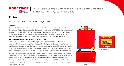
In Building 2 Way Emergency Radio Communication System ERCES Amplifier System offers all the components required for design and installation of the Radio Communication Enhancement Systems ERCES signal boosters Amplifiers BDA batteries and battery enclosures donor antennas Antenna Systems DAS coaxial cables connectors and lightning power dividers and hybrid couplers design services and training Boosters Bi Directional Amplifiers BDA Class B BDAs are high gain high power band selective signal amplifiers that can be designed and customized to meet all safety frequency band ranges It is intended to provide reliable two way radio coverage inside buildings tunnels and other structures The band selective delivers a reliable performance in even the most challenging RF environments of the art design delivers high reliability and excellent performance in a small and economical package Gamewell FCI Class B BDAs have been tested evaluated in accordance with UL2524 requirements for In building 2 Way Radio Communication Enhancement Systems NFPA and IBC IFC compliance it the best choice for public safety and other mission applications BENEFITS All public safety bands various available for GW BDA400 1B GW BDA150 1B MHz GW BDA800 MHz GW BDA700 and 800MHz UL CSFM NFPA IFC and fully signal booster BDA with UL2524 In 2 Way Radio Systems CSFM Listing 72 2010 Edition 1221 2016 Edition IFC 2018 Does not external DC supplies chargers alarm interfaces or dual power system with two AC circuit Integrated battery function intelligent monitoring and with load testing hour Battery Backup the standard battery package Gamewell FCI Monitor MMI 10F in to connect to SLC loop monitoring of the BDA the fire alarm control six alarm relay for the BDA Panel a supervised annunciator with 6 status lights Normal AC Power Loss AC power BDA Trouble Trouble Battery Trouble and Battery The panel on the standard 2 gang box and does not require power Diagnostics Each is monitored for voltage and any antenna line with the RF EOL Logged On a SD integrated SD logger records all conditions and messages with a stamp into a text file Auxiliary Alarm Displays BDA Supply Unit PSU Test Function activate the troubles to test annunciator NEMA 4 Type UL Approved Reliability using the highest quality components and the latest RF by major US Manufacturers and manufactured using state of the art manufacturing Country of Origin USA Form Factor and light fully integrated signal booster heavy gauge aluminum NEMA 4 type UL type 4 approved is lightweight and has excellent heat dissipating and resistance properties high efficiency power supplies are included for redundancy mounting tabs for easy wall mounting Conduit cutouts on the underside of the enclosure Padlock tabs are included of Use and Deployment field tuning or programming required Unit ships tuned and tested the factory to use gain and power settings LCD displays the BDA and PSU status and trouble along with basic system diagnostics ALC LED light indication of signal strength two circuit breakers with screw terminals directly above the power conduits for easy connection of AC power circuits quick disconnect terminals for fire alarm and dedicated panel connections EOL resistors are selectable with the DIP switch if needed Design with easy to swap and easy to test modules module has a status indication LED light for easy and status monitoring clutter free design with easily accessible components accessible RF connectors modules are typically in stock and available for quick from the factory year warranty excluding battery Design allows for easy updates and frequency band boosters can be combined on the same antenna system for operation module has an internal microcontroller that continuously its operation and measures the voltage temperature and other parameters ALC Automatic Level Control circuits prevent RF power and RF interference Detection Circuit prevents amplifier feedback and Uplink Squelch Completely eliminates uplink noise from BDA by shutting off uplink amplifier while it is idle achieving no from within the building and eliminating risk of public safety radio network RF Performance modules provide high rejection of interfering signals Multiple channels bands are possible the same amplifier performance bandpass cavity type duplexers minimize out of interference Gain of up to 92dB on both uplink and downlink ensures the coverage area capacity even with very weak signals Power capable of producing up to 32dBm of RF power to cover very large indoor areas Linearity Amplifiers deliver signals with very low distortion and IM products Resilient to strong RF inputs ensures optimal intermod free even in a highly congested performance even in high RF environments with signals as as 20dBm low signal delay of 9us means no delay produced RF distortion the signal overlap areas noise figure ensures that even the weakest signals of under are amplified and boosted well above the noise floor not only for FM and phase 1 P25 but also for TDMA and 2 P25 modulations RF gain on both LNA Low Noise Amplifier and ALC maximum power level ALC OLC Output Level Control circuits maintain the set limit and prevent the power amplifier overload Specifications Range Bandwidth each Gain adjustable Adjustment 1 dB increments Composite Output i e single carrier max Limiter Adjustment 1 attenuator increments RF Signal Input for FCC spurious limits Maximum Input RF Level Figure indications Logger Power Supply Supply Efficiency Power Supply Time with standard 60 de rated Battery Charging with the Charger2 Temperature3 ID Certifications UHF 150 174MHz VHF 3MHz1 max typ max typ Uplink MHz Uplink MHz Uplink 763 775 MHz Typ to 92dB 42dB total adjustment range to 18dBm 30dBm to 16dBm to 16dBm 30dBm to 16dBm to 14dBm typ 8dB typ 8dB typ 8dB max 6.5dB typ 8dB max typ 7dB max Power Status Charger Status Low Battery Capacity BDA Trouble Antenna Trouble and Aux Alarm Second relay Form C relays for each of the troubles set provided for a LED annunciator panel SD Card up to 16GB Mini SD with adapter Real time clock time stamp included independent power supplies with 110 240VAC 2.1A 50 60Hz each two 2 75Ah 12V AGM Sealed L A batteries in series for Secondary power Maximum Current Draw 2.5A Ohm continuous 10dBm peak Typ Hours under full load Current Limited to 5A max to 77 F 20 to 25 2AHVPSB800M2A Title 47 Part 90 FCC Title 47 Part 15b channels can be combined within the 3MHZ duplexer band pass Multiple