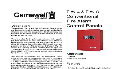
Gamewell-FCI Flex 4 and Flex 8 Fire Panels

File Preview
Click below to download for free
Click below to download for free
File Data
| Name | gamewell-fci-flex-4-and-flex-8-fire-panels-6523487901.pdf |
|---|---|
| Type | |
| Size | 800.69 KB |
| Downloads |
Text Preview
Flex 4 Flex 8 Alarm Panels Flex 4 Class B Style B or 2 A Style D Initiating Device and 2 Class A B Style Z Y Appliance Circuits Flex 8 Class B Style B or 4 A Style D Initiating Device and 4 Class A B Style Z Y Appliance Circuits Initiating Device Circuits IDCs be individually configured for General Alarm zones Waterflow 3 or 3 7 Supervisory 4 or 4 8 Alarm Verification zones Supervisory operation may be Latch or Non Latching Notification Appliance Circuits may be programmed as Silenceable Non Silenceable Auto Silenceable Coded March Time Temporal California Code 5.0 Amps of total NAC power Common Alarm Supervisory and contacts Resettable four wire smoke detec power 100 mA Integral Walk Test operation EIA 485 interface for up to 3 model Remote Annunciators Polarity Reversal and City Tie con with optional PRM module Optional Digital Alarm Communica Transmitter module DACT Relay by zone capability with RY4 4 or RY8 Flex 8 modules Circuit Expander Module CEM Flex 4 IDC capacity Sheet D150 Flex 4 and Flex 8 Fire Alarm Panels from Gamewell are for small to medium com industrial occupancies Sim and easy configuration of the controls is via DIP switches product flexibility allows with the specific job at each installation standard configurations are The Flex 4 includes 4 B Style B Initiating Device IDCs which are easily and wired to perform 2 Class A Style D circuits For an alarm condition the 4 provides 2 Notification Ap Circuits NACs that may wired for Class A B Style Z Y and are rated for up to 1.7 Amperes each twice the circuit capacity the 8 provides 8 Class B IDCs are easily configurable as 4 A circuits and 4 Class A B Each NAC is also rated for maximum of 1.7 Amps with to notification appliance power for Flex 8 at 5 Amps maximum Flex 4 may be expanded in the to provide the circuit capacity a Flex 8 by installing a Circuit Module CEM The provides an additional 4 B 2 Class A IDCs and 2 A or B NACs initiating circuits of the Flex 4 Flex 8 are factory set to oper for Class B Style B wiring Through field pro all circuits can easily converted to Class A Style D integral 6 Amp power supply is in both products to pro system power 4 wire re smoke power 24 VDC mA and up to 5 Amps of noti appliance power Flex 4 and Flex 8 use simple switches programming and NACs as well as ena and disabling of system such as signal silence drill and auxiliary disconnect circuits may be config for audible or visual devices silenceable or non silence operation continued Flex 4 and Flex 8 allow for verification on all Initiating Circuits IDCs Prede IDCs may be optionally con for Waterflow zone 3 Flex or zones 3 7 Flex 8 or Non Latching Supervi zone 4 Flex 4 or zones 4 Flex 8 and Approvals UL 864 Standard for Control for Fire Alarm Systems NFPA 72 National Fire Alarm compliance State Fire CSFM MEA NYC Material and Equip Acceptance Division Type Auxiliary using PRM Re Station Protected Premises DACT or PRM Central Protected Premises using of Service Signaling M WF SS SS is only Local or DACT Non coded Specifications 4 Flex 8 Fire Alarm Control Panels Input Power 102 VAC 60 Hz 4 Amps Power Two 12 volt batteries in series Charging Capacity Up to 24 Ampere Hours max Device Circuits 26 VDC 3 mA standby 1.5Vp p ripple 50 mA max alarm power limited Compatibility Identifier Output Power 6 Amps maximum Output Ratings 24 VDC unfiltered 1.7 Amps max circuit 5 Amps max power limited Power Output 24 VDC unfiltered 300 mA max power limited Smoke Power 28 VDC unfiltered 100 mA max 1.5Vp p ripple resettable power limited Consumption 110 mA standby 220 mA alarm Circuit Board Fuse 10 Amps Relays Alarm Trouble Supervisory 1 Amp resistive 28VDC Form C Connection Connects up to 3 RA8 Remote Indication Output Controls single RTI Remote Trouble Indicator resistor 30177 3.9 K Ohm 1 2 Watt 5 with spade lugs Listed 4 Flex 8 Optional Modules Annunciator 8 Zone Current Consumption 35 mA standby 90 mA alarm Trouble Buzzer Current Consumption 35 mA standby 35 mA alarm Alarm Communicator Transmitter Current Consumption 45 mA standby 120 mA alarm Module 4 Form C Current Consumption 5 mA standby 160 mA alarm 1 Amp resistive 28 VDC Module 8 Form C Current Consumption 5 mA standby 160 mA alarm 1 Amp resistive 28 VDC Reversal City Tie Module Current Consumption 35 mA standby 300 mA alarm Supervised City Tie 24 VDC unfiltered 210 mA max 14 Ohms trip coil NOT power limited Polarity Reversal 24 VDC open 12 VDC 3.5 mA 8 mA max shorted power limited Expander Module Flex 4 only Current Consumption 45 mA standby 120 mA alarm Initiating Device Circuits 22 VDC 3 mA standby 1.5Vp p ripple 50 mA max alarm power limited IDC Compatibility Identifier NAC Output Ratings 24 VDC unfiltered 1.7 Amps max circuit power limited Specifications Dimensions 14 H x 14 W x 5 D Space Two 12 AH batteries max Specifications Humidity 10 non condensing Rating 0 49 32 120 Information Description 4 Four zone expandable microprocessor based Fire Alarm Control Panel with 4 Class B Style or 2 Class A Style D Initiating Device Circuits IDCs 2 Class A B Style Z Y Notification Circuits NACs and a 6 Amp power supply Expandable up to 8 Class B Style B or 4 Class A Style D and 4 Class A B Style Z Y NACs Allows for installation of one Digital Alarm Communicator Transmitter or one PRM Polarity Reversal City Tie Module one RY4 or RY8 Auxiliary Relay Module Red surface or flush mount enclosure with CAT key locked door