Gamewell-FCI L-Series Emergency Communication Devices

File Preview
Click below to download for free
Click below to download for free
File Data
| Name | gamewell-fci-l-series-emergency-communication-devices-5083462791.pdf |
|---|---|
| Type | |
| Size | 678.47 KB |
| Downloads |
Text Preview
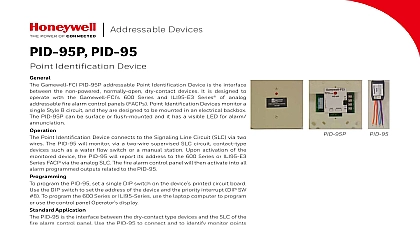
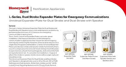
Notification Appliances Emergency Communication Devices L Series Emergency Communications devices and accessories combine versatility with all of the same time saving and cost effective benefits of L Series product line The L Series devices are the broadest and most versatile line of notification devices available and include a wide range of devices to the emergency communications application requirements model visual signaling text labeled ALERT is printed on the white housing lens strobes and speaker strobes This visual signaling label is used to identify emergency communications in compliance with ANSI UL 1638 Standard for Signaling Visible Appliances Other Plain or ALERT printed models provide lenses for use with the following color lens strobe attachments amber green blue red models can easily connect to a strobe and speaker strobe devices without a derating In addition the L Series Emergency Communications devices plain non printed strobes horn strobes and speaker strobes These devices with the ALERT printed devices and L Series accessories can meet a wide of requirements for indoor applications including the following emergency communications emergency response general signaling severe weather Communication Device L Series Emergency Communications and general signaling devices are compatible with the entire L Series product line and they include same time saving and cost effective innovations For example the devices provide the following added benefits plug in design simplifies the installation and reduces costly ground faults universal mounting plates with on board shorting springs test wiring continuity to reduce the installation time frame and protect the from damage The field selectable settings provide versatility and enable Installers to quickly set each device to comply with the requirements BENEFITS Designed with Plain or white Includes either Clear or lens strobes and strobes Contains color lens for use clear lens wall or strobes Complies with DoD Features Offers a plug in design operation at 15 30 candela simplified and Built with a mounting shorting spring to test the wiring Provides an automatic of 12 or 24 Supports the following settings Wall 15 30 75 95 135 185 Ceiling 15 30 75 95 150 177 Rated from 32 to indoor devices to 151 NEMA IP56 weatherproof Includes an optional Torx screw Compatible with the Disabilities Act requirements for visible signaling flashing at 1 Hz over the strobe entire voltage range The strobe light shall consist a xenon flash tube and associated lens reflector The horn shall have three audible options and option to switch between a temporal three pattern a non temporal continuous pattern These shall be set by a multiple position switch The and horn strobe models shall operate on a coded non coded power supply Strobe Combination speaker strobe shall be an L Series Model listed to UL Standard 1480 and UL 1971 and be approved for fire protective systems Speaker shall be capable of at 25.0 or 70.7 nominal VRMS selected via switch and shall have a frequency range of 400 4,000 Hz Speaker shall have power taps that are by rotary switch The strobe shall comply with NFPA 72 requirements for visible signaling flashing at 1 Hz over the strobe entire voltage range The strobe light shall consist a xenon fl ash tube and associated lens reflector Module module shall be a Sync model MDL3 listed UL Standard 464 and shall be approved for fire service The module shall synchronize L strobes at 1 Hz and horns at temporal three operating the strobes the module shall silence horns on horn strobe models over a single pair of The module shall mount to a 4 11 16 x 4 11 16 2 1 8 back box The module shall also control two Y Class B circuits or one Style Z Class A circuit module shall synchronize multiple zones Daisy two or more synchronization modules will synchronize all the zones they control The do not operate on a coded power supply Lens Strobe Attachment L Series color lens attachments shall be approved fire protective service as listed in UL Standard The lens attachments shall only be used with non fire printed strobe devices They shall to any wall or ceiling strobe and shall be rated minus 35 degrees to 151 degrees Fahrenheit Specifications Specifications General L Series strobes and horn strobes shall mount to of the following standard 4 x 4 x 1 1 2 inch backbox 4 inch octagon backbox double gang backbox L Series compact mounts to a single gang 2 x 4 x 7 8 inch backbox The L Series speaker strobes shall to a 4 x 4 x 2 1 8 inch backbox A universal plate shall be used for mounting ceiling and products The notification appliance circuit wiring amplifier wiring shall terminate at the universal plate Continued The L Series products when used with the Module accessory shall be powered a non coded notification appliance circuit and shall operate on a nominal 12 or 24 volts When the L Series products are used the Sync Module the outputs will as follows 12 volt rated notification appliance circuit outputs operate with between 8.5 and 17.5 volts 24 volt rated notification appliance circuit outputs operate between 16.5 and 33 volts indoor L Series products shall operate between 32 120 degrees Fahrenheit from a regulated DC or rectified unfiltered power supply horn strobes and speaker strobes shall have following field selectable candela settings 15 115 30 135 95 177 110 185 75 159 clear strobe shall be an L Series Model to UL Standard 1971 and shall be approved for protective service Colored lens strobes shall be to ANSI UL Standard 1638 and shall be for Private Mode Emergency The strobe shall wired as a primary signaling notification appliance comply with the Americans with Disabilities Act for visible signaling appliances flashing 1 Hz over the strobe entire operating voltage range strobe light shall consist of a xenon flash tube and lens reflector system Strobe Combination horn strobe shall be an L Series Model to UL Standard 1971 and UL Standard 464 and be approved for fire protective service The horn shall be wired as a primary signaling appliance and comply with the Americans 1 lists the Speaker Sound output Sound Ouput Reverberant dBA 10 ft 2 W 1 W 1 2 W 1 4 W SPS Series SPC Series 85 82 85 82 1 Speaker Sound Output Current Draw 2 lists the UL maximum strobe current draw mA Volts 16 Volts Candela Settings 15 30 75 95 115 150 177 Candela Settings 15 30 75 95 110 135 2 UL Max Strobe Current Draw RMS Current Draw Data 3 lists the maximum UL current draw mA RMS allowed for 2 Wire Horn Strobes VDC VDC 30 Temp Hi Temp Low Cont Hi Cont Low Temp Hi Temp Low 91 Cont Hi 156 52 Cont Low FWR Temp Hi Temp Low Cont Hi Cont Low Temp Hi Temp Low 68 Cont Hi Cont Low Candela Settings 15 30 75 95 115 150 177 Candela Settings 15 30 75 95 110 135 185