Gamewell-FCI L-Series Indoor Wall Horns, Strobes, and Horn Strobes

File Preview
Click below to download for free
Click below to download for free
File Data
| Name | gamewell-fci-l-series-indoor-wall-horns-strobes-and-horn-strobes-5623871049.pdf |
|---|---|
| Type | |
| Size | 1.35 MB |
| Downloads |
Text Preview
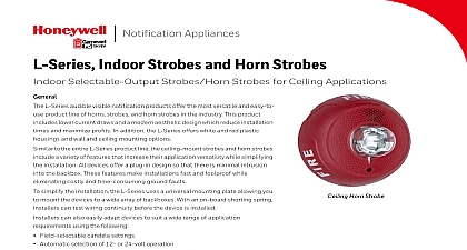
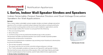
Notification Appliances Indoor Strobes and Horn Strobes Selectable Output Horns Strobes and Horn Strobes for Wall Applications L Series audible visible notification products offer the most versatile and easy to line of horns strobes and horn strobes in the industry In addition this product lower current draws and a modern aesthetic design which reduce installation and maximize profits following devices offer a variety of design options so that the L Series can be for any application requirement White and red plastic housings Standard and small footprint devices Plain FIRE and FUEGO printed devices to the entire L Series product line the wall mount horns strobes and horn include a variety of features that increase their application versatility while the installation All devices offer a plug in design so that there is minimal into the backbox These features make installations fast and foolproof while costly and time consuming ground faults further simplify the installation and protect devices from construction damage the uses a mounting plate for all standard and compact models that include an shorting spring This feature allows Installers to test wiring continuity before device is installed Horn Horn Strobe can also easily adapt devices to suit a wide range of application requirements using the following features Field selectable candela settings Automatic selection of 12 or 24 volt operation Rotary switch for horn tones with two volume selections BENEFITS Uses field selectable settings on units Listed for wall only Offers small profile for horns and strobes Provides an automatic of 12 or 24 operation at 15 30 candela Produces horn rated at dBA at 16 volts 15 30 75 95 110 135 185 Includes a mounting for all standard all compact wall Contains a mounting with a shorting that checks the continuity device Features a plug in Supports a rotary with minimal into the for horn tone two volume Designed with a Current Draw 1 lists the UL maximum strobe current draw Volts 16 33 Volts 1 UL Maximum Strobe Current Draw mA RMS 2 lists the UL maximum Horn current draw KHz Temporal KHz Temporal KHz Non Temporal High KHz Non Temporal KHz Coded 2 UL Max Horn Current Draw mA RMS Volts FWR 95 30 150 75 177 Specifications it is used with the Sync Module the following 12 volt rated notification appliance circuit outputs shall between 8.5 and 17.5 volts 24 volt rated notification appliance circuit outputs shall between 16.5 and 33 volts Indoor L Series products shall operate between 32 and degrees Fahrenheit from a regulated DC or full wave unfiltered power supply Strobes and horn strobes have the following field selectable candela settings 15 115 strobe shall be an L Series Model listed to UL 1971 and shall be approved for fire protective service strobe shall be wired as a primary signaling notification and comply with the Americans with Disabilities Act for visible signaling appliances flashing at 1 Hz the strobe entire operating voltage range The strobe light consist of a xenon flash tube and associated lens system Strobe Combination horn strobe shall be an L Series Model listed to UL 1971 and UL Standard 464 and shall be approved for protective service The horn strobe shall be wired as a notification appliance and comply with the with Disabilities Act requirements for visible appliances flashing at 1 Hz over the strobe entire voltage range The strobe light shall consist of a flash tube and associated lens reflector system The shall have two audible options and an option to switch a temporal three pattern and a non temporal pattern These options are set by a multiple switch The horn on horn strobe models shall operate a coded or non coded power supply Module module shall be a Sync model MDL3 listed to UL 464 and shall be approved for fire protective service module shall synchronize SpectrAlert strobes at 1 Hz and at temporal three Also while operating the strobes the shall silence the horns on horn strobe models over a pair of wires module shall mount to a 4 11 16 x 4 11 16 x 2 1 8 inch The module shall also control two Style Y Class B or one Style Z Class A circuit The module shall multiple zones Daisy chaining two or more modules together will synchronize all the they control The module shall not operate on a coded supply Current Draw Data 3 lists the maximum UL Current Draw mA RMS allowed for Wall Horn Strobes Temp Hi Temp Low Cont Hi Cont Low Temp Hi Temp Low Cont Hi Cont Low Volts FWR Input Temp Hi Temp Low Cont Hi Cont Low Temp Hi Temp Low 68 Cont Hi Cont Low Volts 3 UL Max Current Draw mA RMS Wall Horn Strobe Horn Strobe Range 15 115 cd Strobe Tones and Sound Output Data 4 lists the horn strobe tones and sound output date Pattern KHz Temporal KHz Temporal KHz Non Temporal KHz Non Temporal Low KHz Coded Position See Note See Note Settings 9 and 10 are not available on 2 Wire horns and strobes coding must be provided by the NAC If the NAC voltage is held constant the horn output remains on 4 Horn Strobe Tones and Sound Output Data Dimensions mm mm mm mm mm cm cm mm mm 1 Compact Strobe Horn Strobe 2 Compact Horn 3 Compact Wall Surface Mount cm cm mm mm SBBGRL SBBGWL mm cm cm cm cm 4 Strobe Horn Strobe 5 Horn 6 Wall Surface Mount Backbox cm mm Ordering Information Strobes Strobe Red Strobe White Compact Strobe Red Compact Strobe White Strobe Red Plain Strobe White Plain Strobe White ALERT All P models have a plain housing no marking on All SP models have marking on cover All ALERT models have marking on cover Ordering Information HRL Horn Red HWL Horn White HGRL Compact Horn Red HGWL Compact Horn White Horn only models are listed for wall or ceiling use TR