Hochiki Fiber Optic Network Solution

File Preview
Click below to download for free
Click below to download for free
File Data
| Name | hochiki-fiber-optic-network-solution-0753629148.pdf |
|---|---|
| Type | |
| Size | 1.04 MB |
| Downloads |
Text Preview
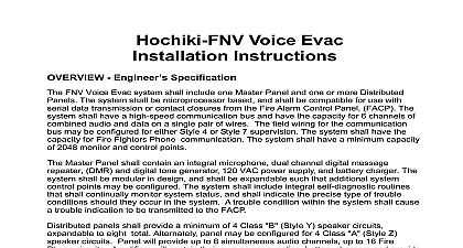
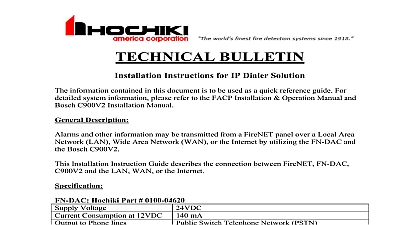
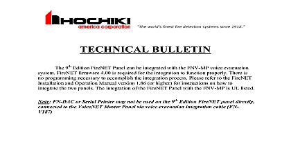
BULLETIN Instructions for Fiber Optic Network Solution information contained in this document is to be used as a quick reference guide For system information please refer to the FACP Installation Operation Manual TCF 142 series Installation Manual and IFS D1300 series Installation Manual Description FireNET system enables information to be transmitted between control panels using a network connection Up to 64 control panels or network annunciators nodes can be together and the system can be configured such that selected information can be or acted upon at each panel Installation Instruction Guide describes the network connection between panels or panel network annunciator to connect and communicate over a Single Multi Mode Fiber Optic through the following data transceiver products MOXA TCF 142 Series GE Security D1300 Series TCF 142 Series Voltage Consumption at 12VDC Distance Temperature Security D1300 Series Voltage Consumption at 12VDC Distance Temperature Release 09 03 2010 1.00 48VDC mA Single Mode 24.8 Miles 40km Multi Mode 3.1 Miles 5km 40 167 75 x 3.94 x 0.87 24VDC mA Single Mode 20 Miles 33km Multi Mode 1.9 Miles 3km 40 165 74 x 4.9 x 1.0 Please refer to the MOXA GE Security datasheet for detailed specifications on the above products Scheme designing or installing a network of FireNET panels and network annunciators always aware of the following The panel network must be wired as a ring Class A Each fiber run will require two links connected to another panel or panels Up to 64 control panels or annunciators can be connected together in one loop If either of these is not a trouble will be displayed It is important to ensure the connection from terminals from one panel connect to the terminals of the next panel so on The terminals of the last panel are connected to the terminals the first panel to complete the loop Two Fiber Optic converters are required per or network annunciator node Dip Switch settings must be set accordingly to the MOXA wiring diagram Network cabling should be standard RS485 type with minimum 20 AWG and the for the fiber cables Caution for Wire Types MOXA Single Mode 9 125 8.3 125 8.7 125 10 125 MOXA Multi Mode 50 125 62.5 125 and 100 140 GE Security Single Mode 9 125 GE Security Multi Mode 62.5 125 Diagrams Release 09 03 2010 1.00 1 MOXA TCF 142 Series Figure 2 GE Security D1300 Series you have any questions regarding this matter please contact Technical Support Support Release 09 03 2010 1.00