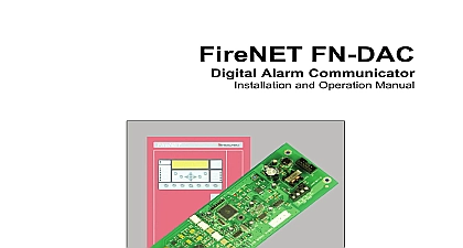
Hochiki FireNET graphix Manual rev 2 0

File Preview
Click below to download for free
Click below to download for free
File Data
| Name | hochiki-firenet-graphix-manual-rev-2-0-0936485127.pdf |
|---|---|
| Type | |
| Size | 2.84 MB |
| Downloads |
Text Preview
graphix Fire Alarm System Graphics Software Installation and Programming 2.0 Overview 3 Installing the hardware 3 PC Connection 4 Software Installation 5 FireNET graphix Run 6 Running FireNET graphix 6 FireNET graphix Settings 8 Application tab options 9 Behaviour tab 10 Graphics Events tab 11 Audio tab 16 Status Panels tab 17 Quiet Message tab 18 About tab 18 User Setup 18 Security Code 19 FireNET graphix Service 19 View Maps 20 View Loop Devices 20 View Zones 20 Print Current Event 20 Event Log 20 Map Windows 20 Minimize 21 Log off Administrator 21 Shutdown FireNET 21 Event Pane 21 Designer 21 Map Options 22 Working with Map Links 22 Adding Devices to Maps 23 Toolbars 24 BMPGrabber 25 graphix Manual revision 2.0 Page 2 of 26 Overview graphix is a software program that allows a PC to display events in text and or graphical form as they occur the FireNET fire alarm system Up to 64 FireNET control panels may be connected to a PC running FireNET graphix graphix also allows a user to take control of the fire alarm system via a replica of a fire alarm control panel on the PC display FireNET graphix records all events from the fire alarm system and allows these events to filtered and presented for analysis in a variety of ways connect a FireNET fire alarm system to a PC running FireNET graphix software a dongle device must be installed in of the control panels and connected to a serial port on the PC If the fire alarm system consists of more than one control panel information from the other control panels is transmitted over the fire alarm network to the panel is connected to the PC dongle is protected by a security code This code is assigned by Hochiki America Corporation After the security has been entered it will only work on the FireNET panel on which it was originally installed Please see section of this manual for details on obtaining and entering the security code FireNET graphix system can be connected to a single fire alarm control panel or a network of control panels by up 3,900 feet 1,200 metres of suitable RS 485 data cable the FireNET graphix host computer is connected to a Local Area Network LAN the FireNET graphix system may be enhanced by use of FireNET graphix workstation displays Up to 15 FireNET graphix workstations can display and control the FireNET network more details on using FireNET graphix workstations please contact Hochiki America Corporation Installing the hardware hardware consists of two parts the dongle circuit board PCB which is installed in a FireNET control panel and RS232 RS485 converter which is located at the computer dongle provides an isolated interface to the FireNET panel and allows the data from the FireNET graphix to be sent and received The FireNET graphix software cannot communicate with the fire panel unless a has been installed and the security code has been enabled dongle is supplied with a ribbon cable to connect it to the FireNET display board The dongle must also be with 24 VDC operating power This can be provided by the FireNET control panel auxiliary power To avoid damage to the dongle and other equipment all connections must be made while AC power batteries are disconnected removing power at the control panel install the dongle circuit board in the accessory module location in the enclosure The accessory module location is to the right of the main board four standoffs are provided to the dongle Next connect and route the 10 way ribbon cable from the dongle to J5 on the front board of the panel Once in place the ribbon cable should be secured with the self adhesive clips provided the red power wire from the dongle to the Aux 24V terminal on the FireNET panel terminal 18 the black power wire from the dongle to the Aux 24V terminal on the FireNET panel terminal 19 4 CORE data cable suitable for RS 485 data communications should be installed between the FireNET panel and the This data cable should be connected to the terminals marked T T R and R on the dongle graphix Manual revision 2.0 Page 3 of 26 PC Connection hardware supplied with the FireNET graphix dongle includes an RS232 RS485 converter The RS232 RS485 enables data to be transmitted over greater distances than the few feet p


