Hochiki IP Dialer Solution - 07122010

File Preview
Click below to download for free
Click below to download for free
File Data
| Name | hochiki-ip-dialer-solution-07122010-4307621895.pdf |
|---|---|
| Type | |
| Size | 790.50 KB |
| Downloads |
Text Preview
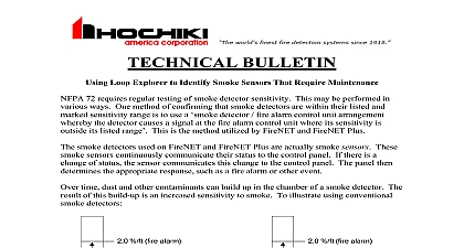
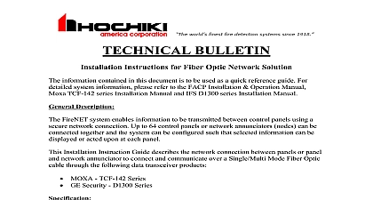
BULLETIN Instructions for IP Dialer Solution information contained in this document is to be used as a quick reference guide For system information please refer to the FACP Installation Operation Manual and C900V2 Installation Manual Description and other information may be transmitted from a FireNET panel over a Local Area LAN Wide Area Network WAN or the Internet by utilizing the FN DAC and Bosch C900V2 Installation Instruction Guide describes the connection between FireNET FN DAC and the LAN WAN or the Internet Hochiki Part 0100 04620 Voltage Consumption at 12VDC to Phone lines Temperature Hochiki Part 0100 04625 Voltage Consumption at 12VDC to LAN or WAN Temperature mA Switch Telephone Network PSTN 0 120 49 x 7.48 24VDC mA Packets 0 120 49 x 4.5 Please refer to the Bosch C900V2 datasheet for detailed specifications on the above product Format Settings Dip Switch settings enables dialer format setting for the host alarm panel The below is to set the standard dialer formats CID 1 OFF SW 2 OFF SW 3 ON SW 4 OFF 10 ON Release 07 12 2010 1.00 SIA 1 ON SW 2 ON SW 3 OFF SW 4 OFF 10 ON Scheme designing or installing a FN DAC between a FireNET panel and C900V2 always be of the following C900V2 must be installed in a separate enclosure AE2 Red Enclosure Hochiki Part and in the same room as the FireNET Panel within 20 feet Wiring be enclosed in conduit or equivalently protected C900V2 Output 1 and Output 2 must be wired to the FireNET Panel Refer to Supervision section and Figure 2 FN DAC Tip 1 connects to Pin 4 of the Ethernet Cable and Ring 1 connects to Pin 5 the Ethernet cable for phone line 1 connection Refer to Figure 1 Connect a jumper from FN DAC Tip 2 to Tip 1 and Ring 2 to Ring 1 which allows supervision of phone line 1 and 2 Refer to Figure 1 The CAT6 Ethernet cable connects to C900V2 Jack for Primary phone line to Figure 1 Network cabling should be a standard CAT6 Ethernet cable Connect TELCO jack to a telephone line Refer to Figure 1 Supervision order to fully supervise both failure and Failure from the C900V2 below programming instructions and wiring diagram on figure 1 For proper Supervision program the Programmable Input 1 2 Attributes as Input 1 Zone 499 Input Delay NO Input Latch NO Input Action TROUBLE Edit Location Text C900V2 CPU FAILURE Input 2 Zone 500 Input Delay NO Input Latch NO Input Action TROUBLE Edit Location Text C900V2 NETWORK FAILURE Release 07 12 2010 1.00 You must provide the programming configuration of the FireNET programmable 1 and 2 to your Central Station for proper response to these events Zone 499 and should not be used for any other purposes Diagrams 1 Release 07 12 2010 1.00 2R 2L 1R 1L Panel 2 you have any questions regarding this matter please contact Technical Support Support Release 07 12 2010 1.00