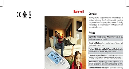
Honeywell Thermostat CM900 User Manual

File Preview
Click below to download for free
Click below to download for free
File Data
| Name | honeywell-thermostat-cm900-user-manual-1683207594.pdf |
|---|---|
| Type | |
| Size | 1.17 MB |
| Downloads |
Text Preview
CM900 Wireless Guide CM921 Wireless Programmable Thermostat BDR91 Relay Box Honeywell CM900 Wireless or is a modern wireless programmable thermostat based on Honeywell proven philosophy To further improve the of use this product includes an extra large display with backlighting and LoT Technology assist customers during daily use CM927 921 room thermostat communicates the BDR91 Relay Box on an 868MHz Radio RF band to control a single heating component such as a boiler pump or valve Neither product will communicate with RF products that use different frequencies or protocols The RF link between the individual room CM927 921 and Relay Box BDR91 system packs provided by Honeywell is pre at the factory and therefore SHOULD installed at the same site This makes the process fast and easy but if products individual system packs are separated or with other pre configured system packs installations please refer to section 5.1 Rebinding Procedure to bind the desired together and allow them to communicate with other of Contents Installation Information 2 Installing the CM900 Wireless System 3 2.1 Installing the Relay Box 3 Installing the Room Thermostat 4 Power Up 4 RF Communication Check 4 Locating the Room Thermostat 5 System Check 5 Basic Operation of the System 6 3.1 Automatic Operation 6 3.2 Temporary Manual Override 6 3.3 Communication Loss 6 Installer Mode 6 4.1 Entering Installer Mode 7 4.2 BDR91 Relay Box Fail Safe Mode Setup 7 Using the Room Thermostat for Specific Applications 8 Using the Special Features of the Room Thermostat 8 Installer Parameters Table 9 Category 1 Room Thermostat Settings 9 Category 2 System Settings 10 Additional Installation Information 11 Binding Rebinding Procedure 11 Multi Zone System 11 Binding an HR80 Radiator Controller to the Room Thermostat 11 Trouble Shooting 12 Trouble Shooting Guide 12 Diagnostics Mode 12 A Installation Information these products communicate using RF technology special care must be taken during installation The of the RF components as well as the building structure may influence performance of the RF To assure system reliability please review and apply the information given below a typical residential building the two products should communicate reliably within a 30m range It important to take into consideration that walls and ceilings will reduce the RF signal The strength of RF signal reaching the Relay Box depends on the number of walls and ceilings separating it from the thermostat as well as the building construction the diagram below illustrates an example of typical strength reduction Walls and ceilings reinforced with steel or plasterboard walls lined with metal foil the RF signal significantly more a position is selected for the room thermostat this can be checked using the RF Communication Test as described in section 2.2.3 Locating the Room Thermostat If the position is unsuitable the Relay will not respond and an alternative position must be selected Signal Strength Signal Length 30 metres example of Building Fabric Signal losses Wireless Programmable Room Thermostat Installing the CM900 Wireless System follow the illustrations and information below in sequence to install the Relay Box and room correctly For applications other than gas boilers enabling special features and to see what system options are available refer to section 4 Installer Mode Installing the Relay Box M3.5 No6 Relay Box is a RF device For the performance install in an open Leave at least 30cm distance any metal objects including wall and boiler housing not mount on metal wall boxes compliance considerations AC mains supply load cables from signal wiring to Code of Practice standards and 2 for guidance direct control The Relay Box contains user serviceable parts It be opened and installed qualified installer only Electrostatic sensi device Do not touch the board boiler valve device All wiring must be in accordance with IEE regulations Observe ambient temperature and current limits the Relay Box wiring label 7mm 7mm max Guide Installing the Room Thermostat Power Up Remove the battery cover and insert the batteries supplied with the room thermostat 2 x AA LR6 On the initial power up the available user interface languages will be displayed only on certain models buttons to cycle through the options until the desired language is displayed Press the or Batteries the button to confirm the selection Set the slider switch to the DATE mode Use the Use the or or buttons to set the correct day month year pressing the green button to buttons to set the correct time pressing the green button to confirm the batteries included and attach the instruction label to flap RF Communication Check Test Mode check the RF communication hold the room thermostat about 2 3 metres from the installed Relay Box the slider on the room thermostat to the OFF position then press the buttons together button for 3 seconds The unit will display TRANSMIT and it will send test signals to the the Box flashing the green LED on every 6 seconds relay output will remain off for a maximum of 10 When the green LED flashes on every 6 seconds proceed to the next step and If the green LED is not switched at specified intervals the red LED is flashing or if you are installing replacement Relay Box or room thermostat follow the procedures described in section 5.1 Binding Procedure Wireless Programmable Room Thermostat Locating the Room Thermostat still in the Test Mode as described in section 2.2.2 the room thermostat should be located taking following into consideration and reviewing the illustrations below Find a suitable location where the signal transmission is reliable Reliable transmission is indicated when Relay Box is flashing the green LED every 6 seconds NOTE The Relay Box relay will be off Install the room thermostat EITHER on the wall using the wall bracket OR attach the optional table stand shown in below Exit the Test Mode by moving the setting slider to the required operating mode AUTO or OFF bracket stand at least 30cm distance from any metal objects including wall boxes and at least 1 metre from any other equipment eg radio TV PC etc System Check a simple test can be completed to check the full system has been installed correctly Set the slider switch to the OFF mode Check the boiler supply is on and check that the green LED on the Relay Box is off Set the slider switch to the MAN mode Adjust the setpoint up to the maximum 35 by pressing the LED ON on Relay Box after a few seconds and the display button The boiler should come on symbol appears on the room thermostat Set the slider switch to the OFF mode The boiler will go off green LED OFF on Relay


