Honeywell Thermostat L7224A,C User Manual

File Preview
Click below to download for free
Click below to download for free
File Data
| Name | honeywell-thermostat-l7224a-c-user-manual-3826051749.pdf |
|---|---|
| Type | |
| Size | 3.17 MB |
| Downloads |
Text Preview
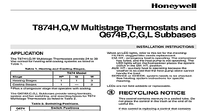
L7224A C L7248A C L Electronic Controllers L7224A C and L7248A C L 2012 Compliant Oil Aquastat Controllers provide electronic sensing in a UL limit rated control with a sensing probe The L7224A C and L7248A C L the circulator oil burner and boiler temperature L7224 L7248 is Temperature Reset ready is enabled when connected to the W8735S1000 Reset Kit Outdoor Reset with the L7224 L7248 intended for all applications except for tankless coil for domestic hot water Compliance to 2012 regulation ensures efficiency is maximized without with domestic hot water demand L7224A C and L7248A C L replace the L8124A L7124A C L7148A and L8148A Controllers L7224A C and L7248A C L series controls provide and diagnostic information through an LED display with LED lights as well as EnviraCOM enabled thermostats and diagnostic to enhance the diagnostic process INSTRUCTIONS Ratings 120 Vac 60 Hz 7 VA maximum at 120 Vac plus external loads current 100 mA nominal at 24 Vac Relay A at 120 Vac Full Load Amperage FLA A inrush Locked Rotor Amperage LRA Ignition Load 360 VA Relay A at 120 Vac FLA 44.4 A inrush LRA Controller ZC 7.4 A at 120 Vac FLA A inrush LRA All loads combined cannot exceed 2000 VA Ratings 30 to 150 34 to 66 0 to 95 relative humidity noncondensing Laboratories Inc Component Recognized Underwriters Laboratories Inc Component Aquastat Controllers are intended for use residential type applications of Outdoor Temperature Reset on a tank coil application requiring a Low Limit setting result in reduced system effectiveness and DOE Compliance and Operation of this control may delay the burner operation while the residual heat is out of the boiler This operation may be different than earlier electronic Aquastat which did not implement thermal purge L7248A C L OIL ELECTRONIC AQUASTAT CONTROLLERS Wireless Outdoor Reset Kit Wireless Outdoor Reset Module Wireless Outdoor Temperature Sensor W8735ER1000 AquaReset Outdoor Reset Kit includes Outdoor Reset Module and Outdoor Temperature Sensor AquaReset Domestic Hot Water Kit 50022037 005 Domestic Hot Water Module 32003971 003 Sensor EnviraCOM Alarm Module Outdoor Temperature Sensor used with the Temperature Sensor used with See Table 2 1 4 in 6.35 mm diameter 1 1 4 in mm long glass cartridge Fuse 1A Slow Blow Heat Conductive Compound Sensor Well Clamp 1 Wells for L7224A C L7248A C L Controllers Size mm mm 1 2 12.7 NPT 3 76.2 3 4 19.05 NPT 3 76.2 mm 38.1 38.1 2 Sensors for L7224A C and L7248A C L Controllers Number in 304.8 Well mounted controls 609.6 Flush mounted controls 914.4 1219.2 Installing this Product Read these instructions carefully Failure to follow could damage the product or cause a condition Check the ratings given in the instructions and on product to make sure the product is suitable for application The installer must be a trained experienced service After installation is complete check out product as provided in these instructions Set High Limit Low Limit and Low Limit Differential the settings recommended by the boiler OEM Record the maximum High Limit setting from the controller in the text box provided on the insert label Record the High Limit setting at time of installation the text box provided on the cover insert label Shock Hazard cause severe injury death or property power supply before beginning to prevent electrical shock or damage L7224A C and L7248A C L models are available in a horizontal position vertical position or flush remote from the well versions Dimensions for variety of mounting options are shown in Fig 1 Note each identity will have only a single mounting option 2 67 109 86 1 4 7 x 3 8 9 1 L7224A C L7248A C L mounting dimensions in inches mm 29 53 L7248A C L OIL ELECTRONIC AQUASTAT CONTROLLERS well must fit sensing element and must rest against bottom of well Installation well assemblies separately see Table 1 and form 68 0040 Immersion Wells and Compression Fittings Temperature Controllers Boilers usually have tappings allow the well to be mounted horizontally so boiler of average temperature can circulate freely over the Turn off all power and drain the boiler if applicable no tapping is provided prepare properly sized and tapping near the top of the boiler Sparingly coat the well threads with pipe dope Do not attempt to tighten by using the case a handle the well in the boiler tapping and tighten Refill boiler and check for water leakage Loosen but do not remove the well clamp screw Fit the case into the well so the clamp on the case over the flange on the well Securely tighten the clamp screw the sensor element into the well until it bot See Replacement Sensor Installation section details If necessary slightly bend the wire the case to hold the sensor against the bot of the well Turn power ON Set High Limit Low Limit and Low Limit Differential the settings recommended by the boiler OEM OPERATION section See INSTALLATION 6 and 7 On L7248L models adjust ELL option to match your see OPERATION section and Fig 11 13 thermal response is obtained with a well snugly fits the sensor Insert the sensor until rests against the bottom of the well Use a well correct length and bend the wiring if neces to hold the bulb against the bottom of the the well is not a snug fit on the sensor use the compound furnished with models as follows Fold the bag of compound lengthwise and twist it Then snip off end of bag and work the end of the bag all the way into the well pull out the bag while squeezing it firmly distribute compound evenly in the well Bend wiring if necessary to hold the sensor the bottom of the well and to hold outer of the sensor in firm contact with the side of well See Fig 2 Wipe excess compound the outer end of the well WIRES CASE COMPOUND CLAMP WELL SCREW 2 Position of sensor in immersion well Aquastat off all power and remove the old control Refer to the insert of the old control to identify and tag each lead as it is disconnected If the old well is for the new installation remove it and replace it a suitable new well If the old well is suitable use it Aquastat off all power and remove the old control Refer to the insert of the old control to identify and tag each lead as it is disconnected If the old well is for the new installation remove it and proceed instructions for new installation If the old well is use it Loosen but do not remove the well clamp screw on side of the control case Position immersion well clamp snugly over the of the adapter and tighten the clamp screw the sensor into the well as shown in Fig 2 or See Replacement Sensor Installation section for 2 1 T HOLES 3 Circuit board showing sensor connection and holes for horizontal mount models L7248A C L OIL ELECTRONIC AQUASTAT CONTROLLERS WIRES