Honeywell Thermostat Q674 User Manual

File Preview
Click below to download for free
Click below to download for free
File Data
| Name | honeywell-thermostat-q674-user-manual-3298570461.pdf |
|---|---|
| Type | |
| Size | 758.69 KB |
| Downloads |
Text Preview
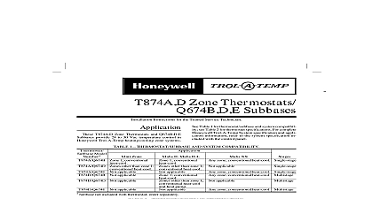
T874H Q W Multistage Thermostats and Subbases T874H Q W Multistage Thermostats provide 24 to 30 control for heating and cooling systems as listed in 1 1 Heating and Cooling Stages Model Stages Stages Plus a changeover stage that operates with cooling Q674B C G L Subbases provide wiring terminals and fan switching and mounting bases for T874 Thermostats as listed in Table 2 2 Switching Positions Positions Ht Heat Off Cool a two stage or three stage heat thermostat the stages heat make sequentially as the temperature drops Make to the mercury switch initiating a call for heat or cool are about 2 1 between the stages so that the stage makes only when the first stage can not the load About one degree later the third stage T874W only This degree difference is called the differential models include LEDs light emitting diodes The lights to indicate a problem with the system refer to system manufacturer instructions INSTRUCTIONS an LED lights refer to this list for the meaning clogged filter needs replacement HT emergency heat is operating The compressor failed and the heat pump is not operating The lights when the homeowner places the system in the EM HT position HT auxiliary heat is operating because the is so cold that the heat pump alone cannot the load or CHECK system needs to be checked heating system instructions for specific are not field addable or replaceable NOTICE control contains mercury in a sealed tube Do place the control in the trash at the end of its life this control is replacing a control that contains in a sealed tube do not place your old in the trash your local waste management authority for regarding the recycling and the proper of this control or of an old control mercury in a sealed tube Installing this Product Read these instructions carefully Failure to follow could damage the product or cause a hazard condition Check the ratings given in the instructions and on product to make sure the product is suitable for application Installer must be a trained experienced service After installation is complete check out product as provided in these instructions 1996 Honeywell Inc All Rights Reserved UL MULTISTAGE THERMOSTATS AND Q674B C G L SUBBASES Disconnect the power supply to prevent shock or equipment damage Run the wires as close as possible to the To prevent interference with the linkage keep the wire length to a Push the excess wire back into the and plug the hole to prevent drafts from the thermostat operation Do not tighten the thermostat captive mount screws to the point of damaging the threads Do not short across the coil terminals on the This can burn out the heat anticipator Never install more than one wire per terminal a factory supplied jumper with a spade is used thermostats are calibrated at the factory using subbases mounted at true level subbase leveling causes thermostat deviation the thermostat about 5 ft 1.5m above the floor in area with good air circulation at average temperature not install the thermostat where it can be affected by drafts or dead spots behind doors and in corners hot or cold air from ducts radiant heat from sun or appliances concealed pipes and chimneys unheated uncooled areas behind the thermostat as an outside wall and Wiring the Subbase the subbase on a wall or horizontal outlet box If mount it on a vertical outlet box order Honeywell part 193121A Adapter Assembly which includes an ring with two screws and a cover plate to cover marks on the wall wiring must comply with local electrical codes and Follow the equipment manufacturer wiring when available install the subbase Prepare a hole for the thermostat wires at the location Run wires to the location Pull about 6 in 152 mm of wire through the hole 18 gauge color coded thermostat cable for wiring When mounting the subbase on a vertical outlet box an adapter ring with the two screws provided the adapter assembly See Fig 1 Pull the wires through the cover plate if used and subbase wire opening Secure the cover plate subbase with the two screws provided but do fully tighten The subbase mounting slots provide for minor out adjustments Level the subbase by using a level and tightening the subbase mounting See Fig 2 2 60 70 80 SCREWS 2 60 70 80 SCREWS 2 NOT INCLUDED WITH UNIT 60 70 80 ACCESSORY PARTS AVAILABLE 193121A 1 Installation on vertical or horizontal outlet box LEVEL 2 OPENING 2 2 FOR SPRING FINGER ON THE TO 12 2 Leveling subbase Connect the system wires to the subbase See Fig through 9 A letter code for identification is near each terminal The terminal barrier straight or conventional wraparound wiring See Fig 3 Either method is accept Run the wires as close as possible to the keeping the wire length to a minimum the excess wire back into the hole Plug the to prevent drafts incorrectly leveled subbase causes the control to deviate from the setpoint MULTISTAGE THERMOSTATS AND Q674B C G L SUBBASES C815A Thermistor T874W only T874W is used with the C815A Thermistor mounted in outdoor section Locate it in an area where it can the true outdoor ambient temperature Avoid the C815A in an area where it is exposed to high or direct sunlight Refer to heat pump instructions for proper mounting STRAIGHT 5 16 in 8 mm WRAPAROUND 7 16 in 11 mm TERMINAL SCREW 3 Wiring connections COMPONENTS SWITCH CHANGEOVER RELAY POWER SUPPLY PROVIDE DISCONNECT MEANS OVERLOAD PROTECTION AS REQUIRED LED ON SELECT MODELS LED 4 T874H Q674C in heating cooling system COMPONENTS ANTICIPATOR SWITCH ANTICIPATOR SUPPLY PROVIDE DISCONNECT MEANS OVERLOAD PROTECTION AS REQUIRED CHANGEOVER RELAY YELLOW LED RED VAC 5 T874H Q674C in heating cooling system with SERVICE LED and FILTER LED MULTISTAGE THERMOSTATS AND Q674B C G L SUBBASES ANTICIPATOR ANTICIPATOR ANTICIPATOR FAN COMPONENTS RELAY POWER SUPPLY PROVIDE DISCONNECT MEANS AND PROTECTION AS REQUIRED 6 T874Q Q674G for heating only system COMPONENTS ANTICIPATOR ANTICIPATOR ANTICIPATOR HEATER ANTICIPATOR ANTICIPATOR POWER SUPPLY PROVIDE DISCONNECT AND OVERLOAD PROTECTION REQUIRED SWITCH HOT THERMISTOR