Honeywell Thermostat Q674D User Manual

File Preview
Click below to download for free
Click below to download for free
File Data
| Name | honeywell-thermostat-q674d-user-manual-2496103587.pdf |
|---|---|
| Type | |
| Size | 737.13 KB |
| Downloads |
Text Preview
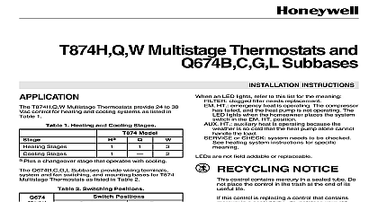
T874A D Zone Thermostats Subbases Instructions for the Trained Service Technician T874A D Zone Thermostats and Q674B D E provide 24 to 30 Vac temperature control in Trol A Temp heating cooling zone systems Table 1 for thermostat subbase and system compatibil see Table 2 for thermostat specifications For complete Trol A Temp System specification and appli information refer to the system specification in with the control panel 1 AND SYSTEM COMPATIBILITY Model Zone 1 conventional II Mabs II L 1 conventional XX zone conventional heat cool Single stage Zones other than zone 1 Zones other than zone 1 Not applicable heat cool Not applicable Not applicable Not applicable heat cool applicable 1 conventional other than zone 1 Not applicable heat cool heat pump applicable zone conventional heat cool Single stage zone conventional heat cool Multistage zone conventional heat cool Multistage Not applicable Subbase not included with thermostat order separately 2 SPECIFICATIONS Numbera White Gray HEAT OFF COOL None HEAT OFF COOL AUTO ON AUTO White Gray HEAT OFF COOL HEAT OFF COOL None None HEAT OFF COOL AUTO ON AUTO White Gray Subbase not included with thermostat order separately Beige Brown White Gray Range A 1 1 to 1.2 to 1.5 1 to 1.2 2 to 1.0 1 to 1.2 2 to 1.0 a 2 heat thermostat the two stages of heat make as the temperature drops Make refers to the switch initiating a call for heat or cool are about 2 F 1 C between stages so that the stage makes only when the first stage cannot the load This is the interstage differential Notice control contains mercury in a sealed tube Do not control in the trash at the end of its useful life this control is replacing a control that contains mercury a sealed tube do not place your old control in the trash your local waste management authority for regarding recycling and the proper disposal of control or of an old control containing mercury in a tube you have questions call Honeywell at 1 800 468 1502 M Rev 6 93 Inc 1993 Form Number 69 0580 1 of subbase on outlet box INSTALLING THIS PRODUCT Read these instructions carefully Failure to fol them could damage the product or cause a hazard condition Check the ratings given in the instructions and on product to make sure the product is suitable for your Installer must be a trained experienced service After installation is complete check out product as provided in these instructions Disconnect power supply to prevent electrical or equipment damage To prevent interference with the thermostat keep wire length to a minimum and wires as close as possible to the subbase Do not overtighten thermostat captive mount screws because damage to subbase threads result Do not short across terminals of systems con This can burn out the thermostat heat Thermostats are calibrated at the factory by subbases mounted at true level Inaccurate sub leveling will cause thermostat control deviation by the subbase about 5 ft 1.5 m above the floor in area with good air circulation at average temperature not mount the subbase where the thermostat may be drafts or dead spots behind doors and in corners hot or cold air from ducts radiant heat from sun appliances or fireplace concealed pipes and chimneys unheated uncooled areas such as an outside wall the thermostat THE SUBBASE thermostat subbase can be mounted on a horizontal box or directly on the wall To mount on a horizontal outlet box install the sub on the outlet box as shown in Fig 1 a wall installation hold the subbase in position and holes for the anchors Fig 2 Obtain wall anchors Take care that the wires do not fall back into the opening Set aside subbase Drill two 3 16 in 4.8 mm and gently tap anchors into the holes until flush with the Pull electrical wires through the cover plate if used subbase cable opening Fig 3 See Wiring the Sub section before pulling any wires Use 18 gauge color coded thermostat for proper wiring Secure the subbase with the screws provided Do not tighten the subbase screws INCLUDED WITH UNIT 2 of subbase on wall THROUGH OPENING 2 3 components and leveling LEVEL 2 OPENING 2 2 FOR SPRING FINGER ON THE TO 12 Level the subbase using a spirit level as shown in 3 and firmly tighten the subbase mounting screws subbase mounting holes allow minor out of level An incorrectly leveled subbase will cause temperature control to deviate from set point THE SUBBASE wiring must comply with local electrical codes and Follow equipment manufacturer wiring in when available To wire subbase Connect wires to the subbase terminals Refer to 6 10 for wiring diagrams of typical zone systems A code is located near each subbase terminal for identi The terminal barrier permits straight or conven wraparound wiring connection Fig 4 Some Q674 Subbases have RC and RH terminals isolated heating and cooling transformers For zoning jumper RC and RH terminals as shown in Fig 5 wire as single R terminal Firmly tighten each terminal screw Fit wires as close as possible to the subbase Push wire back into hole Plug the hole with nonflammable insulation to pre drafts from affecting the thermostat 4 connections STRAIGHT 5 16 in 8 mm WRAPAROUND 7 16 in 11 mm 5 RC and RH terminals for single system Strip wire 3 4 in 19 mm TERMINAL SCREW 6 hookup for MM 2 Mini zone Control Panel with T874A Thermostat Q674B D Subbase in heating cooling two zone system THERMOSTAT Q674B SUBBASE THERMOSTAT SUBBASE G Y1 RC RH W1 Y2 Y2 RC RH W2 SINGLE 1 2 1 2 V 40 VA SUPPLY PROVIDE DISCONNECT MEANS AND OVERLOAD PROTECTION AS REQUIRED 1 O AND B TERMINALS MUST BE CONNECTED FOR PROPER SYSTEM OPERATION RC AND RH TERMINALS TOGETHER AND WIRE AS SINGLE R TERMINAL NOT CONNECT W2 AND Y2 TERMINALS TO CONTROL PANEL THE THERMOSTAT Remove the thermostat cover by pulling the bottom of the cover outward away from the base until it snaps from the cover clip The cover is hinged at the top and is removed by out at the bottom Carefully remove and discard the polystyrene packing that protects the mercury switches during shipment Turn over the thermostat base and note the spring that engage the subbase contacts Make sure the fingers are not bent flat preventing prope