Honeywell Thermostat SP970A User Manual
File Preview
Click below to download for free
Click below to download for free
File Data
| Name | honeywell-thermostat-sp970a-user-manual-6749831520.pdf |
|---|---|
| Type | |
| Size | 820.03 KB |
| Downloads |
Text Preview
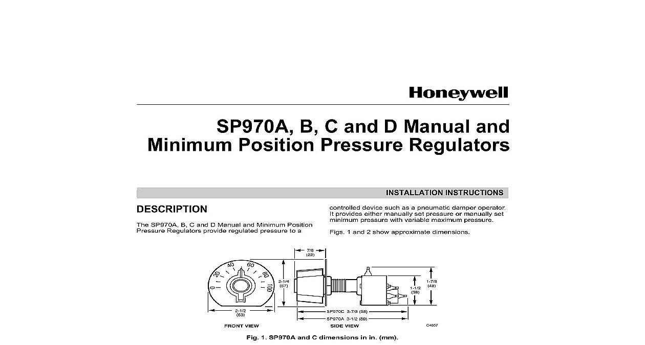
SP970A B C and D Manual and Position Pressure Regulators SP970A B C and D Manual and Minimum Position Regulators provide regulated pressure to a INSTRUCTIONS device such as a pneumatic damper operator provides either manually set pressure or manually set pressure with variable maximum pressure 1 and 2 show approximate dimensions VIEW 3 7 8 98 3 1 2 89 VIEW 1 SP970A and C dimensions in in mm 62 83 VIEW 89 VIEW 2 SP970B and D dimensions in in mm U S Registered Trademark 2002 Honeywell Rights Reserved B C AND D MANUAL AND MINIMUM POSITION PRESSURE REGULATORS scaleplate knob and two mounting nuts furnished with SP970A and C Do not mount the knob during installation to the Calibration section of this docu Mounting the mounting bracket as a template and secure bracket to surface See Fig 4 Screws are not connections are sharp barb 5 32 in 4 mm O D tubing Damage Hazard prevent damage to the sharp barb do not attempt to cut or pull tubing remove the tubing from the barb connections tubing a few inches from the control device a coupling to reconnect tubing When the system is not copper or polyethylene adapt as shown in Fig 5 Some models parts for adapting NUT 1 4 IN 6 MM PLASTIC 1 4 IN MM INSTALLATION and C only panels having a thickness greater than 5 16 in mm but less than one in 25 mm use 315677A Bus SP970A and C can be panel surface or wall The SP970B and D are surface or wall See Fig 3 and 4 PSI PUNCH MARK IN V GROOVE 8 PSI 55 kPa CALIBRATION TO 5 16 IN THICK NUT V IN 16MM HOLE 0 3 SP970A and C panel mounting AND C AND D SWITCH 4 SP970 surface or wall mounting Mounting SP970A and SP970C Drill a 5 8 in 16 mm hole Lock the SP970 switch and scaleplate to the panel a hex nut on the back of the panel Use a sec hex nut on the front panel See Fig 3 FOR IN 4 MM O D TUBING IN 4 MM PLASTIC CUT LENGTH IN X 1 4 IN MM X 6 MM PLASTIC CONNECTOR IN 6 MM PLASTIC CUT TO LENGTH IN 4 MM O D IN 6 MM O D TUBING 5 Adaptation piping Identification Table two right columns in Table 1 identifies the ports of Honeywell pneumatic relays when upgrading B C AND D MANUAL AND MINIMUM POSITION PRESSURE REGULATORS 1 Port Identification Pressure Minimum Position SP970B SP970C D SP970A and C models are calibrated at 8 psi 55 kPa the calibration mark center punch on the shaft is at the bottom of the molded V To calibrate the center punch mark on the shaft with the bottom the molded V groove on the plastic surrounding shaft Fig 3 This setting equals 8 psi 55 kPa Secure the to the shaft at the proper scale setting The knob be pointing to 8 psi 55 kPa See Fig 4 Pressure Switch and Pilot Range Main 18 psi 124 kPa 3 to 15 psi 21 to 103 kPa 3 to 15 psi 21 to 103 kPa Safe Air Pressure 30 psi 207 kPa Operating Limits 0 to 140 18 to 60 Humidity 5 to 95 SP970B and D models are calibrated at 8 psi 55 kPa the knob is set at 50 percent Handling Capacity large range device can be field recalibrated to other points with the same span from 0 psi 0 kPa lower to 26 psi 179 kPa upper limit The small range can be field recalibrated to other end points with same span from 0 psi 0 kPa lower limit to 16 psi kPa upper limit and Test for All Models With main air connected insert a pressure gage the branch line Check pressures equivalent to knob settings When minimum position is used attach input and pilot pressure Verify correct operation DATA SP970A A bleed type pressure regulator SP970B A bleed type pressure regulator mounted a sheet metal panel SP970C A bleed type pressure regulator with a ended pilot chamber for minimum pressure SP970D A bleed type pressure regulator with a ended pilot chamber for minimum pressure mounted on a sheet metal panel Spans for psi kPa See Table 2 2 Selectable Spans Rotationa 34 69 span 55 span 110 The setpoint knob normally rotates 188 degrees Two stops on the knob allow rotation of 244 and degrees 45 90 B above minimum position device feeding determines capacity Below minimum position capacity is 0.022 scfm 10 ml s D 0.022 scfm 10 ml s Consumption 0.022 scfm 10 ml s All models ship with a 0 to 100 scaleplate knob and locknuts Molded plastic with neoprene diaphragm spring and shaft and B Three Port Switches REGULATOR OPERATION line air flows through the restriction into the chamber and out the nozzle Branchline increases until it is strong enough to compress spring and lift the diaphragm off the nozzle Airflow the nozzle is controlled by the balance between the pressure and spring force POSITION OPERATION external signal is connected to port 4 exhaust port the external signal is greater than the spring load nozzle opens and branchline pressure is the same as external signal When the external signal is less than spring load branchline pressure is controlled as in the previous paragraph See Fig 6 6 SP970A B operation B C AND D MANUAL AND MINIMUM POSITION PRESSURE REGULATORS and D Four Port Switches minimum position devices have a separate dead chamber connected to port 3 to receive an signal When the external signal is less than the load the signal has no effect and functions similar the SP970A B as a pressure regulator When the signal is greater than the spring load the spring is isolated and the device duplicates the input See Fig 7 BUILDING TO MINIMUM SETTING PILOT BUILDING BRANCH ABOVE MINIMUM SETTING BALANCED AT MINIMUM SETTING BALANCED AGAINST PILOT 7 SP970C and D operation 8A shows a typical manual position application using three port SP970A B This control system manually a damper between OPEN and CLOSED the setpoint knob clockwise increases the pressure to the damper actuator and opens damper Turning the position knob counterclockwise the branchline pressure and closes the three port SP970A B is also used with a controller automatic damper positioning with minimum position Fig 8B When the external signal is less than the setting the spring maintains the branchline as previously described When the external rises above the knob setting air from the signal directly to the branch During steady state the external automatic controller must be of exha