Honeywell Thermostat T7351F2010 Instructions Manual
File Preview
Click below to download for free
Click below to download for free
File Data
| Name | honeywell-thermostat-t7351f2010-instructions-manual-1749826305.pdf |
|---|---|
| Type | |
| Size | 1.18 MB |
| Downloads |
Text Preview
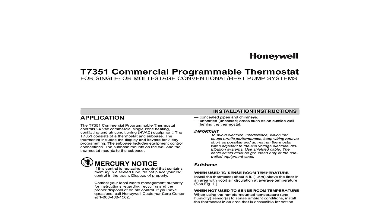
T7351 Commercial Programmable Thermostat SINGLE OR MULTI STAGE CONVENTIONAL HEAT PUMP SYSTEMS T7351 Commercial Programmable Thermostat 24 Vac commercial single zone heating and air conditioning HVAC equipment The consists of a thermostat and subbase The includes the display and keypad for 7 day The subbase includes equipment control The subbase mounts on the wall and the mounts to the subbase NOTICE this control is replacing a control that contains in a sealed tube do not place your old in the trash Dispose of properly your local waste management authority instructions regarding recycling and the disposal of an old control If you have call Honeywell Customer Care Center 1 800 468 1502 Installing this Product Read these instructions carefully Failure to follow could damage the product or cause a hazard condition Check ratings given in instructions and on the to ensure the product is suitable for your must be a trained experienced service After installation is complete check out product as provided in these instructions Shock or Equipment Damage Can shock individuals or short circuitry power supply before installation not install the thermostat where it can be affected by drafts or dead spots behind doors and in corners hot or cold air from ducts radiant heat from sun or appliances INSTRUCTIONS concealed pipes and chimneys unheated uncooled areas such as an outside wall the thermostat avoid electrical interference which can erratic performances keep wiring runs as as possible and do not run thermostat adjacent to the line voltage electrical dis systems Use shielded cable The shield must be grounded only at the con equipment case USED TO SENSE ROOM TEMPERATURE the thermostat about 5 ft 1.5m above the floor in area with good air circulation at average temperature Fig 1 NOT USED TO SENSE ROOM TEMPERATURE using the remote mounted temperature and sensor s to sense ambient conditions install thermostat in an area that is accessible for setting adjusting the temperature and settings the remote mounted sensor s about 5 ft 1.5m the floor in an area with good air circulation at temperature See Fig 1 multiple remote sensors are required they must be in a temperature averaging network consisting four sensors See Fig 2 Only TR21 models with no setpoint adjustment be used for temperature averaging FEET METERS 1 Typical location of thermostat or sensor Bar Code Here COMMERCIAL PROGRAMMABLE THERMOSTAT Subbase subbase mounts horizontally When using the internal temperature or humidity the device must be mounted horizontally the LCD facing upwards Precise leveling not needed When using remote room temperature and sensors thermostat mounting orienta does not matter mounting using standard drywall screws is Mounting to a 2 in by 4 in 50.8 mm by 101.6 wiring box can be accomplished for a horizontal box no extra hardware is required for a vertical box part 209651A is required Mount to European standard wall box having 2.4 in mm between mounting screws in a horizontal with or without adaptive hardware Position and level the subbase A level wallplate is only for appearance thermostat functions properly when level Use a pencil to mark the mounting holes See 3 Remove the subbase from the wall and drill two 3 in 4.8 mm holes in the wall if drywall as For firmer material such as plaster or drill two 7 32 in 5.6 mm holes Gently tap anchors provided into the drilled holes flush with the wall Position the subbase over the holes pulling wires the wiring opening Loosely insert the mounting screws into the holes Tighten mounting screws THROUGH WALL 3 Mounting the subbase Thermostat on Subbase Fig the subbase installed mount the thermostat Engage top subbase tabs into the thermostat top Swing the thermostat down Press the lower edge of the case to latch To remove the thermostat from the wall first pull at the bottom of the thermostat then remove top ENGAGE TABS AT TOP OF THERMOSTAT AND SUBBASE OR WALLPLATE 2 Four TR21 Sensors providing temperature network for T7351 Thermostat PRESS LOWER EDGE OF CASE TO LATCH 4 Mounting thermostat on subbase equipment manufacturer wiring instructions when Refer to the Wiring Diagram section for typical A letter code is located near each terminal for wiring must comply with local electrical codes ordinances Maximum and recommended wire size is 18 Do not use wire smaller than 22 gauge Loosen subbase terminal screws and connect sys wires Securely tighten each terminal screw Push excess wire back into the hole in the wall Plug the hole with nonflammable insulation to pre drafts from affecting the thermostat Thermostat Keys thermostat keys are used to set current time and day program times and setpoints for heating and cooling override the program temperatures display present setting set system and fan operation See Fig 5 for keypad information COMMERCIAL PROGRAMMABLE THERMOSTAT Temperature to Table 2 for the default temperature setpoints To the Occupied and Not Occupied Heat and Cool simply press the Heat and Cool button under Occupied or Not Occupied area of the keypad To set Standby Heat setpoint press both the Occupied and Occupied Heat buttons simultaneous To set the Cool setpoint press the Occupied Cool and Not Heat buttons simultaneously System and Fan default setting is Auto Fan default setting is On Use System and Fan keys to change settings Settings Auto Thermostat automatically changes between and cooling based on indoor temperature Cool Thermostat controls cooling Off Heating cooling and fan are all off Heat Thermostat controls heating Em Heat Auxiliary heat serves as first stage stages are locked off Settings On See Table 1 Auto Fan always cycles with call for heat or cool Conventional The equipment i e plenum switch fan operation in heat mode Thermostat fan operation in cool mode Electric Heat Thermostat controls fan operation in heat and cool modes Fan operation can extend delay Off after the turns off Heating choices are 0 or 90 seconds Cooling choices are 0 or 40 seconds 1 T7351 Intelligent Fan ON control logic for Sensor Sensor Wired Sensed On Fan On On Fan On Motion Sensed On Fan Offa Occupancy is Standby Standby are used and it assumes that the is unoccupied Fan is on only when there a call for heating or cooling Occupied No Sensor Wired Not Occupied Fan On Fan Offa Occupancy sensor will only be active during Occupied Motion Sensed Not Occupied Fan On Fan Offa Occupied No Motion Sensed Not Occupied Fan On Fan Offa Occupied periods During scheduled Occupied periods the effective occupancy always be Not Occupied In heat mode when set for conventional heat the equipment i e plenum switch could power the fan despite the COMMERCIAL PROGRAMMABLE THERMOSTAT Day Time Occupied Occupied Occupied Time COOL AUTO 5 Thermostat key locations SETUP most applications the thermostat factory settings do need to be changed Review the factory settings in 2 combination of key presses are required to use the Setup featu